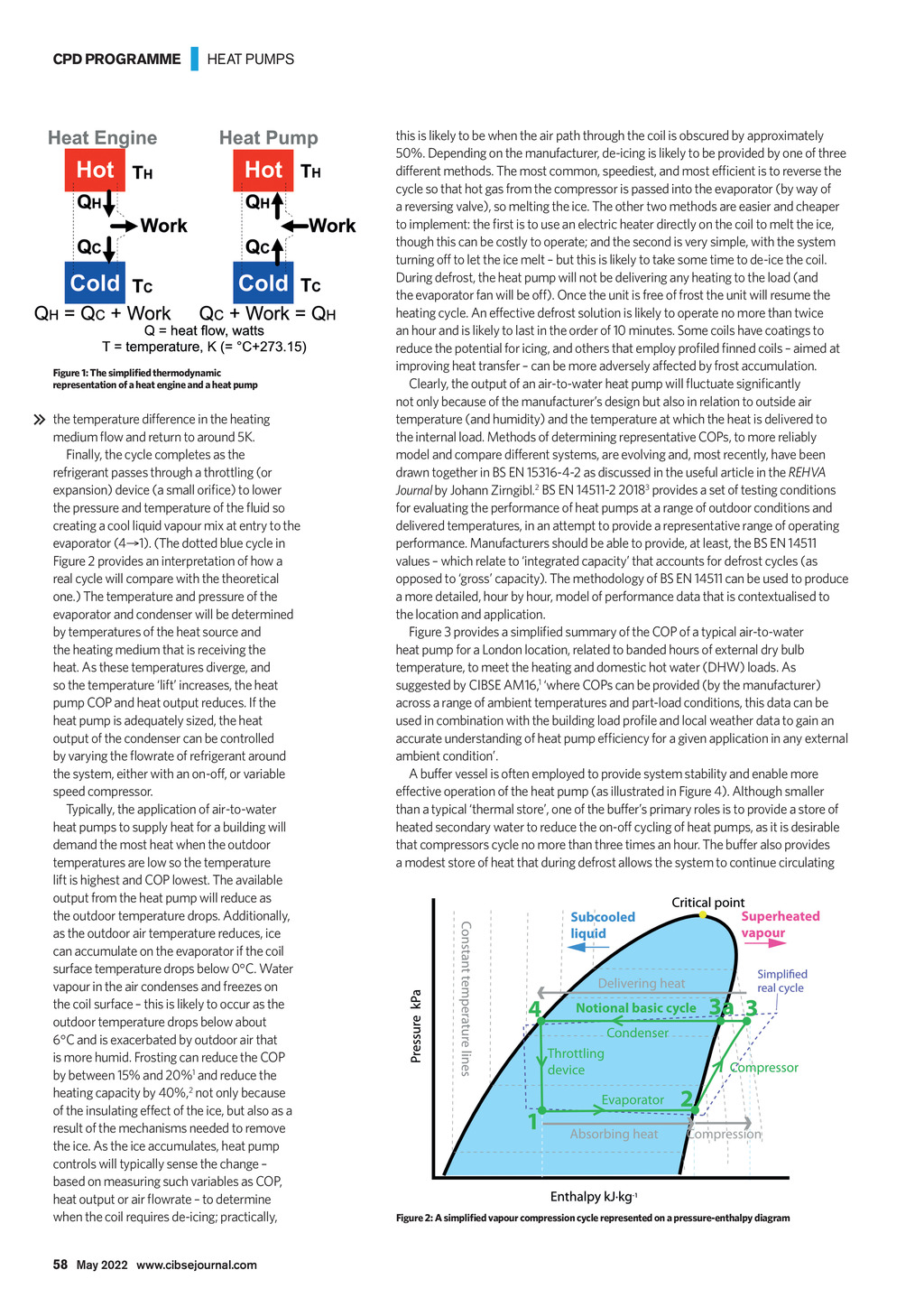


CPD PROGRAMME | HEAT PUMPS Figure 1: The simplified thermodynamic representation of a heat engine and a heat pump the temperature difference in the heating medium flow and return to around 5K. Finally, the cycle completes as the refrigerant passes through a throttling (or expansion) device (a small orifice) to lower the pressure and temperature of the fluid so creating a cool liquid vapour mix at entry to the evaporator (41). (The dotted blue cycle in Figure 2 provides an interpretation of how a real cycle will compare with the theoretical one.) The temperature and pressure of the evaporator and condenser will be determined by temperatures of the heat source and the heating medium that is receiving the heat. As these temperatures diverge, and so the temperature lift increases, the heat pump COP and heat output reduces. If the heat pump is adequately sized, the heat output of the condenser can be controlled by varying the flowrate of refrigerant around the system, either with an on-off, or variable speed compressor. Typically, the application of air-to-water heat pumps to supply heat for a building will demand the most heat when the outdoor temperatures are low so the temperature lift is highest and COP lowest. The available output from the heat pump will reduce as the outdoor temperature drops. Additionally, as the outdoor air temperature reduces, ice can accumulate on the evaporator if the coil surface temperature drops below 0C. Water vapour in the air condenses and freezes on the coil surface this is likely to occur as the outdoor temperature drops below about 6C and is exacerbated by outdoor air that is more humid. Frosting can reduce the COP by between 15% and 20%1 and reduce the heating capacity by 40%,2 not only because of the insulating effect of the ice, but also as a result of the mechanisms needed to remove the ice. As the ice accumulates, heat pump controls will typically sense the change based on measuring such variables as COP, heat output or air flowrate to determine when the coil requires de-icing; practically, this is likely to be when the air path through the coil is obscured by approximately 50%. Depending on the manufacturer, de-icing is likely to be provided by one of three different methods. The most common, speediest, and most efficient is to reverse the cycle so that hot gas from the compressor is passed into the evaporator (by way of a reversing valve), so melting the ice. The other two methods are easier and cheaper to implement: the first is to use an electric heater directly on the coil to melt the ice, though this can be costly to operate; and the second is very simple, with the system turning off to let the ice melt but this is likely to take some time to de-ice the coil. During defrost, the heat pump will not be delivering any heating to the load (and the evaporator fan will be off). Once the unit is free of frost the unit will resume the heating cycle. An effective defrost solution is likely to operate no more than twice an hour and is likely to last in the order of 10 minutes. Some coils have coatings to reduce the potential for icing, and others that employ profiled finned coils aimed at improving heat transfer can be more adversely affected by frost accumulation. Clearly, the output of an air-to-water heat pump will fluctuate significantly not only because of the manufacturers design but also in relation to outside air temperature (and humidity) and the temperature at which the heat is delivered to the internal load. Methods of determining representative COPs, to more reliably model and compare different systems, are evolving and, most recently, have been drawn together in BS EN 15316-4-2 as discussed in the useful article in the REHVA Journal by Johann Zirngibl.2 BS EN 14511-2 20183 provides a set of testing conditions for evaluating the performance of heat pumps at a range of outdoor conditions and delivered temperatures, in an attempt to provide a representative range of operating performance. Manufacturers should be able to provide, at least, the BS EN 14511 values which relate to integrated capacity that accounts for defrost cycles (as opposed to gross capacity). The methodology of BS EN 14511 can be used to produce a more detailed, hour by hour, model of performance data that is contextualised to the location and application. Figure 3 provides a simplified summary of the COP of a typical air-to-water heat pump for a London location, related to banded hours of external dry bulb temperature, to meet the heating and domestic hot water (DHW) loads. As suggested by CIBSE AM16,1 where COPs can be provided (by the manufacturer) across a range of ambient temperatures and part-load conditions, this data can be used in combination with the building load profile and local weather data to gain an accurate understanding of heat pump efficiency for a given application in any external ambient condition. A buffer vessel is often employed to provide system stability and enable more effective operation of the heat pump (as illustrated in Figure 4). Although smaller than a typical thermal store, one of the buffers primary roles is to provide a store of heated secondary water to reduce the on-off cycling of heat pumps, as it is desirable that compressors cycle no more than three times an hour. The buffer also provides a modest store of heat that during defrost allows the system to continue circulating Figure 2: A simplified vapour compression cycle represented on a pressure-enthalpy diagram 58 May 2022 www.cibsejournal.com CIBSE May 22 pp57-60 CPD 196 ELCO Supp.indd 58 22/04/2022 15:57