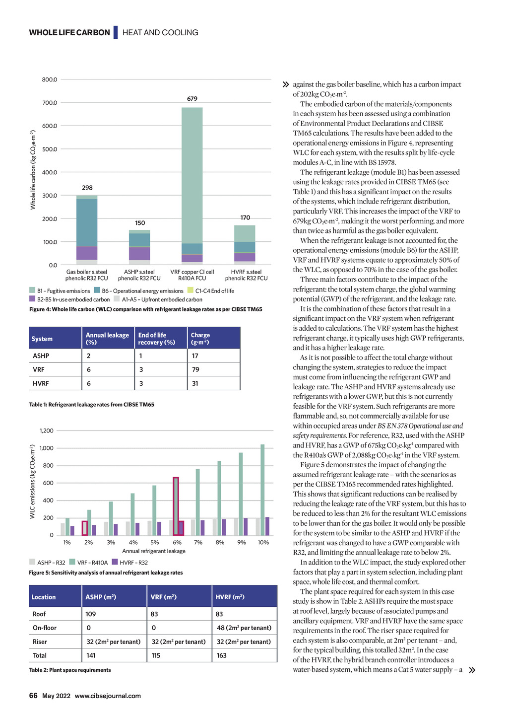


WHOLE LIFE CARBON | HEAT AND COOLING 800.0 679 Whole life carbon (kg CO2e.m-2) 700.0 600.0 500.0 400.0 298 300.0 200.0 170 150 100.0 0.0 Gas boiler s.steel phenolic R32 FCU ASHP s.steel phenolic R32 FCU VRF copper CI cell R410A FCU HVRF s.steel phenolic R32 FCU B1 Fugitive emissions B6 Operational energy emissions C1-C4 End of life B2-B5 In-use embodied carbon A1-A5 Upfront embodied carbon Figure 4: Whole life carbon (WLC) comparison with refrigerant leakage rates as per CIBSE TM65 System Annual leakage (%) End of life recovery (%) Charge (g.m-2) ASHP 2 1 17 VRF 6 3 79 HVRF 6 3 31 Table 1: Refrigerant leakage rates from CIBSE TM65 WLC emissions (kg CO2e.m-2) 1,200 1,000 800 600 400 200 0 1% 2% 3% 4% 5% 6% Annual refrigerant leakage 7% 8% 9% 10% ASHP R32 VRF R410A HVRF R32 Figure 5: Sensitivity analysis of annual refrigerant leakage rates Location ASHP (m2) VRF (m2) HVRF (m2) Roof 109 83 83 On-floor 0 0 48 (2m2 per tenant) Riser 32 (2m2 per tenant) 32 (2m2 per tenant) 32 (2m2 per tenant) Total 141 115 163 Table 2: Plant space requirements against the gas boiler baseline, which has a carbon impact of 202kg CO2e.m-2. The embodied carbon of the materials/components in each system has been assessed using a combination of Environmental Product Declarations and CIBSE TM65 calculations. The results have been added to the operational energy emissions in Figure 4, representing WLC for each system, with the results split by life-cycle modules A-C, in line with BS 15978. The refrigerant leakage (module B1) has been assessed using the leakage rates provided in CIBSE TM65 (see Table 1) and this has a significant impact on the results of the systems, which include refrigerant distribution, particularly VRF. This increases the impact of the VRF to 679kg CO2e.m-2, making it the worst performing, and more than twice as harmful as the gas boiler equivalent. When the refrigerant leakage is not accounted for, the operational energy emissions (module B6) for the ASHP, VRF and HVRF systems equate to approximately 50% of the WLC, as opposed to 70% in the case of the gas boiler. Three main factors contribute to the impact of the refrigerant: the total system charge, the global warming potential (GWP) of the refrigerant, and the leakage rate. It is the combination of these factors that result in a significant impact on the VRF system when refrigerant is added to calculations. The VRF system has the highest refrigerant charge, it typically uses high GWP refrigerants, and it has a higher leakage rate. As it is not possible to affect the total charge without changing the system, strategies to reduce the impact must come from influencing the refrigerant GWP and leakage rate. The ASHP and HVRF systems already use refrigerants with a lower GWP, but this is not currently feasible for the VRF system. Such refrigerants are more flammable and, so, not commercially available for use within occupied areas under BS EN 378 Operational use and safety requirements. For reference, R32, used with the ASHP and HVRF, has a GWP of 675kg CO2e.kg-1 compared with the R410as GWP of 2,088kg CO2e.kg-1 in the VRF system. Figure 5 demonstrates the impact of changing the assumed refrigerant leakage rate with the scenarios as per the CIBSE TM65 recommended rates highlighted. This shows that significant reductions can be realised by reducing the leakage rate of the VRF system, but this has to be reduced to less than 2% for the resultant WLC emissions to be lower than for the gas boiler. It would only be possible for the system to be similar to the ASHP and HVRF if the refrigerant was changed to have a GWP comparable with R32, and limiting the annual leakage rate to below 2%. In addition to the WLC impact, the study explored other factors that play a part in system selection, including plant space, whole life cost, and thermal comfort. The plant space required for each system in this case study is show in Table 2. ASHPs require the most space at roof level, largely because of associated pumps and ancillary equipment. VRF and HVRF have the same space requirements in the roof. The riser space required for each system is also comparable, at 2m2 per tenant and, for the typical building, this totalled 32m2. In the case of the HVRF, the hybrid branch controller introduces a water-based system, which means a Cat 5 water supply a 66 May 2022 www.cibsejournal.com CIBSE May 22 pp64-66, 68 Whole life carbon cooling and heating.indd 66 22/04/2022 18:13