


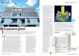


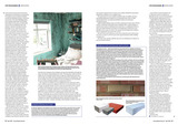


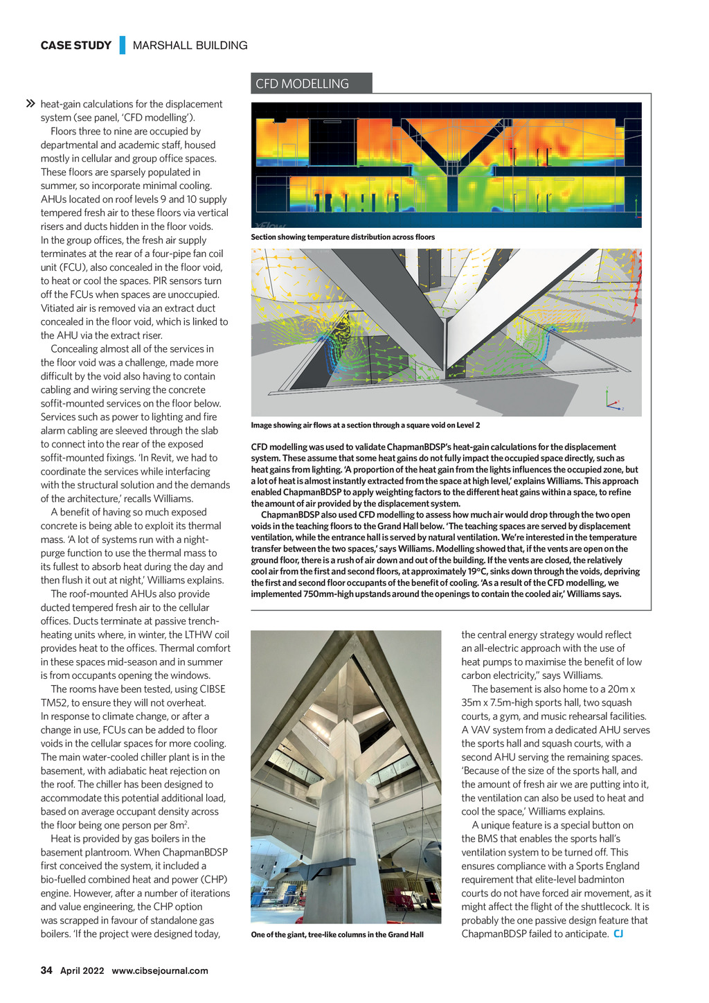


CASE STUDY | MARSHALL BUILDING CFD MODELLING heat-gain calculations for the displacement system (see panel, CFD modelling). Floors three to nine are occupied by departmental and academic staff, housed mostly in cellular and group office spaces. These floors are sparsely populated in summer, so incorporate minimal cooling. AHUs located on roof levels 9 and 10 supply tempered fresh air to these floors via vertical risers and ducts hidden in the floor voids. In the group offices, the fresh air supply terminates at the rear of a four-pipe fan coil unit (FCU), also concealed in the floor void, to heat or cool the spaces. PIR sensors turn off the FCUs when spaces are unoccupied. Vitiated air is removed via an extract duct concealed in the floor void, which is linked to the AHU via the extract riser. Concealing almost all of the services in the floor void was a challenge, made more difficult by the void also having to contain cabling and wiring serving the concrete soffit-mounted services on the floor below. Services such as power to lighting and fire alarm cabling are sleeved through the slab to connect into the rear of the exposed soffit-mounted fixings. In Revit, we had to coordinate the services while interfacing with the structural solution and the demands of the architecture, recalls Williams. A benefit of having so much exposed concrete is being able to exploit its thermal mass. A lot of systems run with a nightpurge function to use the thermal mass to its fullest to absorb heat during the day and then flush it out at night, Williams explains. The roof-mounted AHUs also provide ducted tempered fresh air to the cellular offices. Ducts terminate at passive trenchheating units where, in winter, the LTHW coil provides heat to the offices. Thermal comfort in these spaces mid-season and in summer is from occupants opening the windows. The rooms have been tested, using CIBSE TM52, to ensure they will not overheat. In response to climate change, or after a change in use, FCUs can be added to floor voids in the cellular spaces for more cooling. The main water-cooled chiller plant is in the basement, with adiabatic heat rejection on the roof. The chiller has been designed to accommodate this potential additional load, based on average occupant density across the floor being one person per 8m2. Heat is provided by gas boilers in the basement plantroom. When ChapmanBDSP first conceived the system, it included a bio-fuelled combined heat and power (CHP) engine. However, after a number of iterations and value engineering, the CHP option was scrapped in favour of standalone gas boilers. If the project were designed today, Section showing temperature distribution across floors Image showing air flows at a section through a square void on Level 2 CFD modelling was used to validate ChapmanBDSPs heat-gain calculations for the displacement system. These assume that some heat gains do not fully impact the occupied space directly, such as heat gains from lighting. A proportion of the heat gain from the lights influences the occupied zone, but a lot of heat is almost instantly extracted from the space at high level, explains Williams. This approach enabled ChapmanBDSP to apply weighting factors to the different heat gains within a space, to refine the amount of air provided by the displacement system. ChapmanBDSP also used CFD modelling to assess how much air would drop through the two open voids in the teaching floors to the Grand Hall below. The teaching spaces are served by displacement ventilation, while the entrance hall is served by natural ventilation. Were interested in the temperature transfer between the two spaces, says Williams. Modelling showed that, if the vents are open on the ground floor, there is a rush of air down and out of the building. If the vents are closed, the relatively cool air from the first and second floors, at approximately 19C, sinks down through the voids, depriving the first and second floor occupants of the benefit of cooling. As a result of the CFD modelling, we implemented 750mm-high upstands around the openings to contain the cooled air, Williams says. One of the giant, tree-like columns in the Grand Hall the central energy strategy would reflect an all-electric approach with the use of heat pumps to maximise the benefit of low carbon electricity, says Williams. The basement is also home to a 20m x 35m x 7.5m-high sports hall, two squash courts, a gym, and music rehearsal facilities. A VAV system from a dedicated AHU serves the sports hall and squash courts, with a second AHU serving the remaining spaces. Because of the size of the sports hall, and the amount of fresh air we are putting into it, the ventilation can also be used to heat and cool the space, Williams explains. A unique feature is a special button on the BMS that enables the sports halls ventilation system to be turned off. This ensures compliance with a Sports England requirement that elite-level badminton courts do not have forced air movement, as it might affect the flight of the shuttlecock. It is probably the one passive design feature that ChapmanBDSP failed to anticipate. CJ 34 April 2022 www.cibsejournal.com CIBSE Apr 22 pp32-34 Marshall Building Supp.indd 34 25/03/2022 17:36