


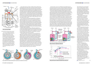


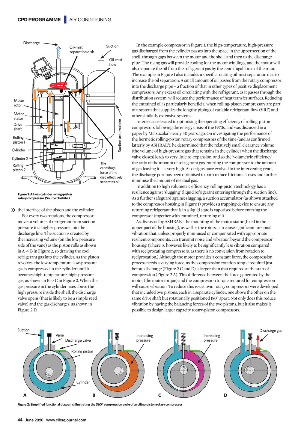

CPD PROGRAMME | AIR CONDITIONING Discharge Oil-mist separation disk Suction Oil-mist flow Motor rotor Suction accumulator Motor stator Drive shaft Rolling piston 1 Cylinder 1 Cylinder 2 The centrifugal force of the disc effectively separates oil Rolling piston 2 Figure 1: A twin-cylinder rolling-piston rotary compressor (Source: Toshiba) the interface of the piston and the cylinder. For every two rotations, the compressor moves a volume of refrigerant from suction pressure to a higher pressure, into the discharge line. The suction is created by the increasing volume (on the low pressure side of the vane) as the piston rolls as shown in A -> B in Figure 2, so drawing the cool refrigerant gas into the cylinder. As the piston revolves, the low-temperature, low-pressure gas is compressed in the cylinder until it becomes high-temperature, high-pressure gas, as shown in B -> C in Figure 2. When the gas pressure in the cylinder rises above the high pressure inside the shell, the discharge valve opens (that is likely to be a simple reed valve) and the gas discharges, as shown in Figure 2 D. In the example compressor in Figure 1, the high-temperature, high-pressure gas discharged from the cylinder passes into the space in the upper section of the shell, through gaps between the motor and the shell, and then to the discharge pipe. The rising gas will provide cooling for the motor windings, and the motor will also separate the oil from the refrigerant gas by the centrifugal force of the rotor. The example in Figure 1 also includes a specific rotating oil-mist separation disc to increase the oil separation. A small amount of oil passes from the rotary compressor into the discharge pipe a fraction of that in other types of positive displacement compressors. Any excess oil circulating with the refrigerant, as it passes through the distribution system, will reduce the performance of heat transfer surfaces. Reducing the entrained oil is particularly beneficial when rolling-piston compressors are part of a system that supplies the lengthy piping of variable refrigerant flow (VRF) and other similarly extensive systems. Interest accelerated in optimising the operating efficiency of rolling-piston compressors following the energy crisis of the 1970s, and was discussed in a paper by Matsuzaka2 nearly 40 years ago. On investigating the performance of the hermetic rolling-piston rotary compressors of the time (and as confirmed latterly by ASHRAE1), he determined that the relatively small clearance volume (the volume of high-pressure gas that remains in the cylinder when the discharge valve closes) leads to very little re-expansion, and so the volumetric efficiency the ratio of the amount of refrigerant gas entering the compressor to the amount of gas leaving it is very high. As designs have evolved in the intervening years, the discharge port has been optimised to both reduce frictional losses and further minimise the amount of residual gas. In addition to high volumetric efficiency, rolling-piston technology has a resilience against slugging (liquid refrigerant entering through the suction line). As a further safeguard against slugging, a suction accumulator (as shown attached to the compressor housing in Figure 1) provides a trapping device to ensure any returning refrigerant that is in a liquid state is vaporised before entering the compressor (together with entrained, returning oil). As discussed by ASHRAE,1 the mounting of the motor stator (fixed in the upper part of the housing), as well as the rotors, can cause significant torsional vibration that, unless properly minimised or compensated with appropriate resilient components, can transmit noise and vibration beyond the compressor housing. (There is, however, likely to be significantly less vibration compared with reciprocating compressors, as there is no conversion from rotation to reciprocation.) Although the motor provides a constant force, the compression process needs a varying force, as the compression rotation torque required just before discharge (Figure 2 C and D) is larger than that required at the start of compression (Figure 2 A). This difference between the force generated by the motor (the motor torque) and the compression torque required for compression will cause vibration. To reduce this issue, twin rotary compressors were developed that included two pistons, each in a separate cylinder, one above the other on the same drive shaft but rotationally positioned 180 apart. Not only does this reduce vibration by having the balancing forces of the two pistons, but it also makes it possible to design larger capacity rotary-piston compressors. Suction Discharge gas Vane Increasing pressure Discharge valve Increasing pressure Rolling piston Cylinder A B C D Figure 2: Simplified functional diagrams illustrating the 360 compression cycle of a rolling-piston rotary compressor 44 June 2020 www.cibsejournal.com CIBSE June 2020 p43-46 CPD Toshiba 163 v2.indd 44 22/05/2020 17:45