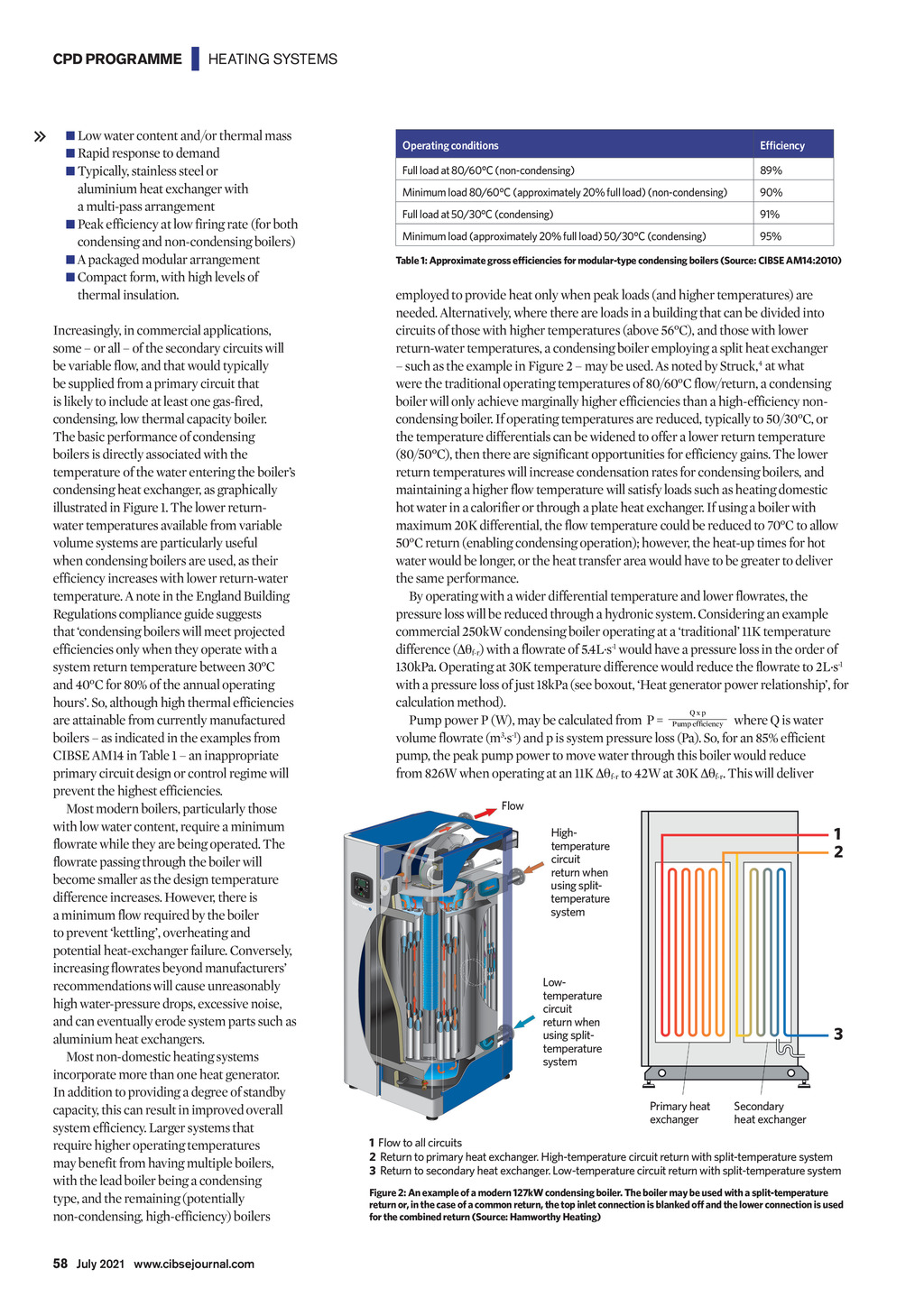


CPD PROGRAMME | HEATING SYSTEMS Low water content and/or thermal mass Rapid response to demand Typically, stainless steel or aluminium heat exchanger with a multi-pass arrangement Peak efficiency at low firing rate (for both condensing and non-condensing boilers) A packaged modular arrangement Compact form, with high levels of thermal insulation. Increasingly, in commercial applications, some or all of the secondary circuits will be variable flow, and that would typically be supplied from a primary circuit that is likely to include at least one gas-fired, condensing, low thermal capacity boiler. The basic performance of condensing boilers is directly associated with the temperature of the water entering the boilers condensing heat exchanger, as graphically illustrated in Figure 1. The lower returnwater temperatures available from variable volume systems are particularly useful when condensing boilers are used, as their efficiency increases with lower return-water temperature. A note in the England Building Regulations compliance guide suggests that condensing boilers will meet projected efficiencies only when they operate with a system return temperature between 30C and 40C for 80% of the annual operating hours. So, although high thermal efficiencies are attainable from currently manufactured boilers as indicated in the examples from CIBSE AM14 in Table 1 an inappropriate primary circuit design or control regime will prevent the highest efficiencies. Most modern boilers, particularly those with low water content, require a minimum flowrate while they are being operated. The flowrate passing through the boiler will become smaller as the design temperature difference increases. However, there is a minimum flow required by the boiler to prevent kettling, overheating and potential heat-exchanger failure. Conversely, increasing flowrates beyond manufacturers recommendations will cause unreasonably high water-pressure drops, excessive noise, and can eventually erode system parts such as aluminium heat exchangers. Most non-domestic heating systems incorporate more than one heat generator. In addition to providing a degree of standby capacity, this can result in improved overall system efficiency. Larger systems that require higher operating temperatures may benefit from having multiple boilers, with the lead boiler being a condensing type, and the remaining (potentially non-condensing, high-efficiency) boilers Operating conditions Full load at 80/60C (non-condensing) 89% Minimum load 80/60C (approximately 20% full load) (non-condensing) 90% Full load at 50/30C (condensing) 91% Minimum load (approximately 20% full load) 50/30C (condensing) 95% employed to provide heat only when peak loads (and higher temperatures) are needed. Alternatively, where there are loads in a building that can be divided into circuits of those with higher temperatures (above 56C), and those with lower return-water temperatures, a condensing boiler employing a split heat exchanger such as the example in Figure 2 may be used. As noted by Struck,4 at what were the traditional operating temperatures of 80/60C flow/return, a condensing boiler will only achieve marginally higher efficiencies than a high-efficiency noncondensing boiler. If operating temperatures are reduced, typically to 50/30C, or the temperature differentials can be widened to offer a lower return temperature (80/50C), then there are significant opportunities for efficiency gains. The lower return temperatures will increase condensation rates for condensing boilers, and maintaining a higher flow temperature will satisfy loads such as heating domestic hot water in a calorifier or through a plate heat exchanger. If using a boiler with maximum 20K differential, the flow temperature could be reduced to 70C to allow 50C return (enabling condensing operation); however, the heat-up times for hot water would be longer, or the heat transfer area would have to be greater to deliver the same performance. By operating with a wider differential temperature and lower flowrates, the pressure loss will be reduced through a hydronic system. Considering an example commercial 250kW condensing boiler operating at a traditional 11K temperature difference ( f-r) with a flowrate of 5.4L.s-1 would have a pressure loss in the order of 130kPa. Operating at 30K temperature difference would reduce the flowrate to 2L.s-1 with a pressure loss of just 18kPa (see boxout, Heat generator power relationship, for calculation method). Qxp where Q is water Pump power P (W), may be calculated from P = 3. -1 volume flowrate (m s ) and p is system pressure loss (Pa). So, for an 85% efficient pump, the peak pump power to move water through this boiler would reduce from 826W when operating at an 11K f-r to 42W at 30K f-r. This will deliver Flow 1 2 Hightemperature circuit return when using splittemperature system Lowtemperature circuit return when using splittemperature system 3 Primary heat exchanger Secondary heat exchanger 1 Flow to all circuits 2 Return to primary heat exchanger. High-temperature circuit return with split-temperature system 3 Return to secondary heat exchanger. Low-temperature circuit return with split-temperature system Figure 2: An example of a modern 127kW condensing boiler. The boiler may be used with a split-temperature return or, in the case of a common return, the top inlet connection is blanked off and the lower connection is used for the combined return (Source: Hamworthy Heating) 58 July 2021 www.cibsejournal.com CIBSE July 21 pp57-60 CPD 182.indd 58 25/06/2021 17:04