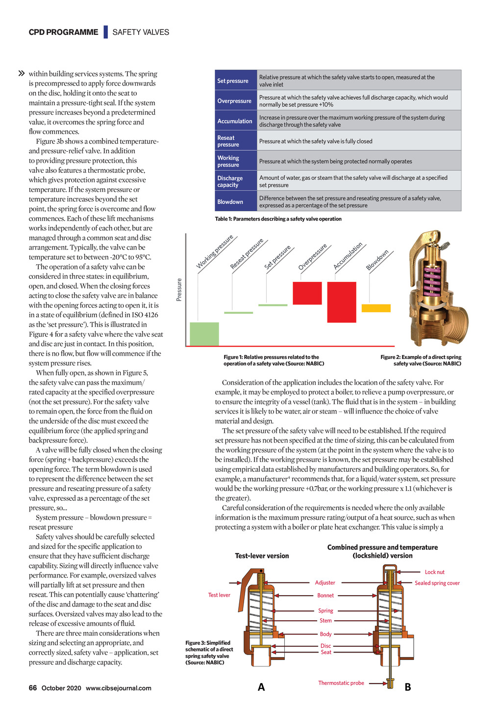


| SAFETY VALVES within building services systems. The spring is precompressed to apply force downwards on the disc, holding it onto the seat to maintain a pressure-tight seal. If the system pressure increases beyond a predetermined value, it overcomes the spring force and flow commences. Figure 3b shows a combined temperatureand pressure-relief valve. In addition to providing pressure protection, this valve also features a thermostatic probe, which gives protection against excessive temperature. If the system pressure or temperature increases beyond the set point, the spring force is overcome and flow commences. Each of these lift mechanisms works independently of each other, but are managed through a common seat and disc arrangement. Typically, the valve can be temperature set to between -20C to 95C. The operation of a safety valve can be considered in three states: in equilibrium, open, and closed. When the closing forces acting to close the safety valve are in balance with the opening forces acting to open it, it is in a state of equilibrium (defined in ISO 4126 as the set pressure). This is illustrated in Figure 4 for a safety valve where the valve seat and disc are just in contact. In this position, there is no flow, but flow will commence if the system pressure rises. When fully open, as shown in Figure 5, the safety valve can pass the maximum/ rated capacity at the specified overpressure (not the set pressure). For the safety valve to remain open, the force from the fluid on the underside of the disc must exceed the equilibrium force (the applied spring and backpressure force). A valve will be fully closed when the closing force (spring + backpressure) exceeds the opening force. The term blowdown is used to represent the difference between the set pressure and reseating pressure of a safety valve, expressed as a percentage of the set pressure, so System pressure blowdown pressure = reseat pressure Safety valves should be carefully selected and sized for the specific application to ensure that they have sufficient discharge capability. Sizing will directly influence valve performance. For example, oversized valves will partially lift at set pressure and then reseat. This can potentially cause chattering of the disc and damage to the seat and disc surfaces. Oversized valves may also lead to the release of excessive amounts of fluid. There are three main considerations when sizing and selecting an appropriate, and correctly sized, safety valve application, set pressure and discharge capacity. 66 October 2020 www.cibsejournal.com CIBSE Oct20 pp65-68 CPD168 NABIC v2.indd 66 Set pressure Relative pressure at which the safety valve starts to open, measured at the valve inlet Overpressure Pressure at which the safety valve achieves full discharge capacity, which would normally be set pressure +10% Accumulation Increase in pressure over the maximum working pressure of the system during discharge through the safety valve Reseat pressure Pressure at which the safety valve is fully closed Working pressure Pressure at which the system being protected normally operates Discharge capacity Amount of water, gas or steam that the safety valve will discharge at a specified set pressure Blowdown Difference between the set pressure and reseating pressure of a safety valve, expressed as a percentage of the set pressure Table 1: Parameters describing a safety valve operation g kin or W e ur ss e pr at se Re e ur ss e pr t Se e ur ss e pr n tio ula wn m do cu w c o A Bl re su es r p er Ov Pressure CPD PROGRAMME Figure 2: Example of a direct spring safety valve (Source: NABIC) Figure 1: Relative pressures related to the operation of a safety valve (Source: NABIC) Consideration of the application includes the location of the safety valve. For example, it may be employed to protect a boiler, to relieve a pump overpressure, or to ensure the integrity of a vessel (tank). The fluid that is in the system in building services it is likely to be water, air or steam will influence the choice of valve material and design. The set pressure of the safety valve will need to be established. If the required set pressure has not been specified at the time of sizing, this can be calculated from the working pressure of the system (at the point in the system where the valve is to be installed). If the working pressure is known, the set pressure may be established using empirical data established by manufacturers and building operators. So, for example, a manufacturer4 recommends that, for a liquid/water system, set pressure would be the working pressure +0.7bar, or the working pressure x 1.1 (whichever is the greater). Careful consideration of the requirements is needed where the only available information is the maximum pressure rating/output of a heat source, such as when protecting a system with a boiler or plate heat exchanger. This value is simply a Test-lever version Combined pressure and temperature (lockshield) version Lock nut Adjuster Test lever Sealed spring cover Bonnet Spring Stem Body Figure 3: Simplified schematic of a direct spring safety valve (Source: NABIC) Disc Seat Thermostatic probe 25/09/2020 17:13