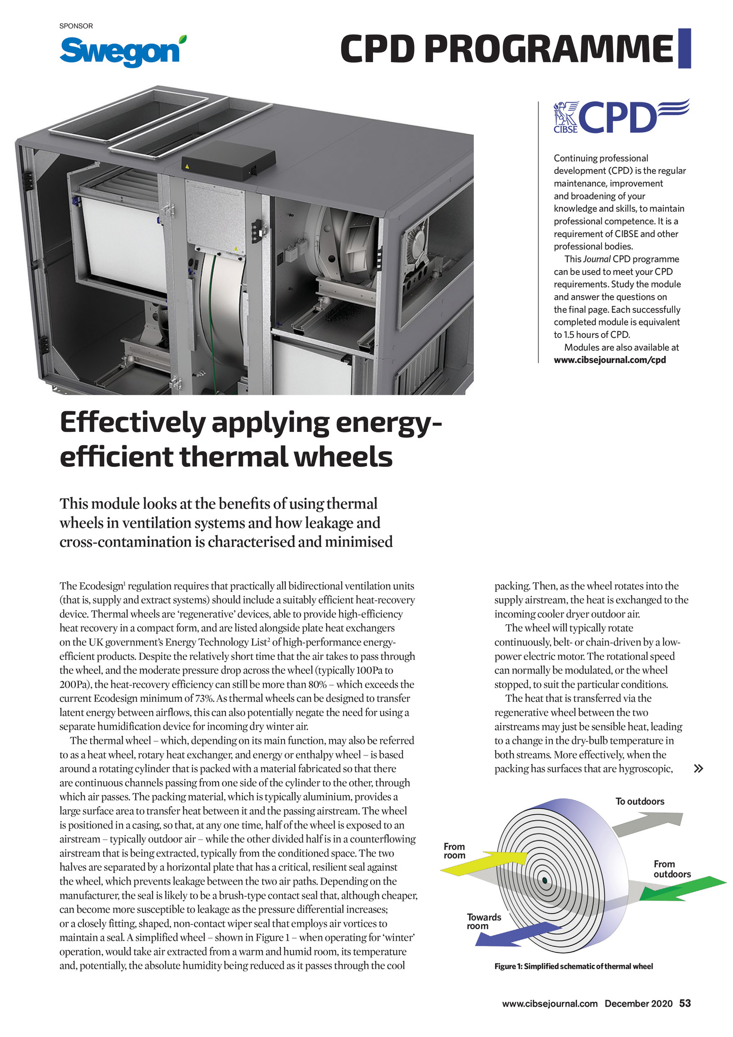
SPONSOR CPD PROGRAMME Continuing professional development (CPD) is the regular maintenance, improvement and broadening of your knowledge and skills, to maintain professional competence. It is a requirement of CIBSE and other professional bodies. This Journal CPD programme can be used to meet your CPD requirements. Study the module and answer the questions on the final page. Each successfully completed module is equivalent to 1.5 hours of CPD. Modules are also available at www.cibsejournal.com/cpd Effectively applying energyefficient thermal wheels This module looks at the benefits of using thermal wheels in ventilation systems and how leakage and cross-contamination is characterised and minimised The Ecodesign1 regulation requires that practically all bidirectional ventilation units (that is, supply and extract systems) should include a suitably efficient heat-recovery device. Thermal wheels are regenerative devices, able to provide high-efficiency heat recovery in a compact form, and are listed alongside plate heat exchangers on the UK governments Energy Technology List2 of high-performance energyefficient products. Despite the relatively short time that the air takes to pass through the wheel, and the moderate pressure drop across the wheel (typically 100Pa to 200Pa), the heat-recovery efficiency can still be more than 80% which exceeds the current Ecodesign minimum of 73%. As thermal wheels can be designed to transfer latent energy between airflows, this can also potentially negate the need for using a separate humidification device for incoming dry winter air. The thermal wheel which, depending on its main function, may also be referred to as a heat wheel, rotary heat exchanger, and energy or enthalpy wheel is based around a rotating cylinder that is packed with a material fabricated so that there are continuous channels passing from one side of the cylinder to the other, through which air passes. The packing material, which is typically aluminium, provides a large surface area to transfer heat between it and the passing airstream. The wheel is positioned in a casing, so that, at any one time, half of the wheel is exposed to an airstream typically outdoor air while the other divided half is in a counterflowing airstream that is being extracted, typically from the conditioned space. The two halves are separated by a horizontal plate that has a critical, resilient seal against the wheel, which prevents leakage between the two air paths. Depending on the manufacturer, the seal is likely to be a brush-type contact seal that, although cheaper, can become more susceptible to leakage as the pressure differential increases; or a closely fitting, shaped, non-contact wiper seal that employs air vortices to maintain a seal. A simplified wheel shown in Figure 1 when operating for winter operation, would take air extracted from a warm and humid room, its temperature and, potentially, the absolute humidity being reduced as it passes through the cool packing. Then, as the wheel rotates into the supply airstream, the heat is exchanged to the incoming cooler dryer outdoor air. The wheel will typically rotate continuously, belt- or chain-driven by a lowpower electric motor. The rotational speed can normally be modulated, or the wheel stopped, to suit the particular conditions. The heat that is transferred via the regenerative wheel between the two airstreams may just be sensible heat, leading to a change in the dry-bulb temperature in both streams. More effectively, when the packing has surfaces that are hygroscopic, To outdoors From room From outdoors Towards room Figure 1: Simplified schematic of thermal wheel www.cibsejournal.com December 2020 53 CIBSE Dec20 pp53-56 CPD 172 Swegon v3.indd 53 20/11/2020 15:07