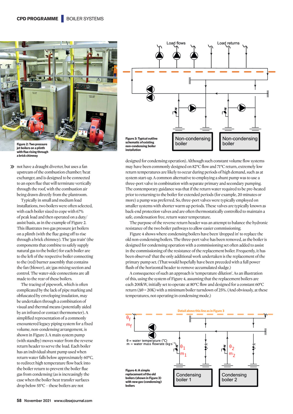


CPD PROGRAMME | BOILER SYSTEMS Figure 2: Two pressure jet boilers on a plinth Figure 3: Typical outline schematic of existing non-condensing boiler installation a brick chimney not have a draught diverter, but uses a fan upstream of the combustion chamber/heat exchanger, and is designed to be connected to an open flue that will terminate vertically through the roof, with the combustion air being drawn directly from the plantroom. Typically in small and medium load installations, two boilers were often selected, with each boiler sized to cope with 67% of peak load and then operated on a duty/ assist basis, as in the example of Figure 2. This illustrates two gas pressure jet boilers on a plinth (with the flue going off to rise through a brick chimney). The gas train (the components that combine to safely supply natural gas to the boiler) for each boiler are to the left of the respective boiler connecting to the (red) burner assembly that contains the fan (blower), air/gas mixing section and control. The water-side connections are all made to the rear of these boilers. The tracing of pipework, which is often complicated by the lack of pipe marking and obfuscated by enveloping insulation, may be undertaken through a combination of visual and thermal means (potentially aided by an infrared or contact thermometer). A simplified representation of a commonly encountered legacy piping system for a fixed volume, non-condensing arrangement, is shown in Figure 3. A main system pump (with standby) moves water from the reverse return header to serve the load. Each boiler has an individual shunt pump used when return water falls below approximately 60C, to redirect high temperature flow back into the boiler return to prevent the boiler flue gas from condensing (as is increasingly the case when the boiler heat transfer surfaces drop below 55C these boilers are not designed for condensing operation). Although such constant volume flow systems may have been commonly designed on 82C flow and 71C return, extremely low return temperatures are likely to occur during periods of high demand, such as at system start-up. A common alternative to employing a shunt pump was to use a three-port valve in combination with separate primary and secondary pumping. The contemporary guidance was that if the return water required to be pre-heated prior to returning to the boiler for extended periods (for example, 20 minutes or more) a pump was preferred. So, three-port valves were typically employed on smaller systems with shorter warm up periods. These valves are typically known as back-end protection valves and are often thermostatically controlled to maintain a safe, condensation free, return water temperature. The purpose of the reverse return header was an attempt to balance the hydronic resistance of the two boiler pathways to allow easier commissioning. Figure 4 shows where condensing boilers have been dropped in to replace the old non-condensing boilers. The three-port valve has been removed, as the boiler is designed for condensing operation with a commissioning set often added to assist in the commissioning of the resistance of the replacement boiler. Frequently, it has been observed1 that the only additional work undertaken is the replacement of the primary pump set. (That would hopefully have been preceded with a full power flush of the horizontal header to remove accumulated sludge.) A consequence of such an approach is temperature dilution. As an illustration of this, using the system of Figure 4, assuming that the replacement boilers are each 200kW, initially set to operate at 80C flow and designed for a constant 60C return ( = 20K) with a minimum boiler turndown of 25%. (And obviously, at these temperatures, not operating in condensing mode.) Detail above this line as in Figure 3 Figure 4: A simple replacement of the old boilers (shown in Figure 3) with new gas (condensing) boilers 58 November 2021 www.cibsejournal.com CIBSE Nov21 pp57-60 CPD 187.indd 58 22/10/2021 16:36