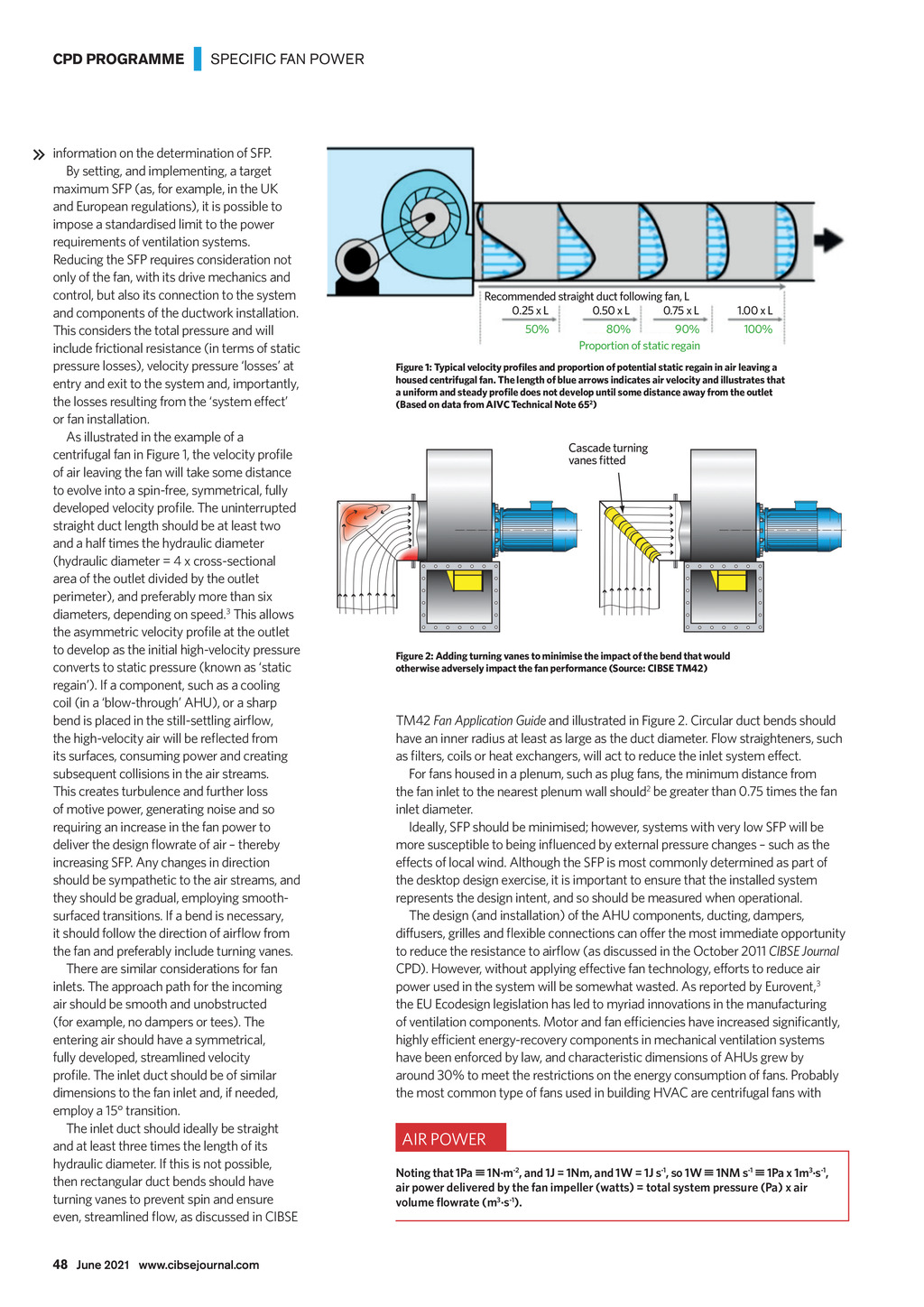


CPD PROGRAMME | SPECIFIC FAN POWER information on the determination of SFP. By setting, and implementing, a target maximum SFP (as, for example, in the UK and European regulations), it is possible to impose a standardised limit to the power requirements of ventilation systems. Reducing the SFP requires consideration not only of the fan, with its drive mechanics and control, but also its connection to the system and components of the ductwork installation. This considers the total pressure and will include frictional resistance (in terms of static pressure losses), velocity pressure losses at entry and exit to the system and, importantly, the losses resulting from the system effect or fan installation. As illustrated in the example of a Recommended straight duct following fan, L 0.25 x L 0.50 x L 0.75 x L 50% 80% 90% Proportion of static regain 1.00 x L 100% ) 2 Cascade turning of air leaving the fan will take some distance to evolve into a spin-free, symmetrical, fully straight duct length should be at least two and a half times the hydraulic diameter (hydraulic diameter = 4 x cross-sectional area of the outlet divided by the outlet perimeter), and preferably more than six diameters, depending on speed.3 This allows to develop as the initial high-velocity pressure converts to static pressure (known as static regain). If a component, such as a cooling coil (in a blow-through AHU), or a sharp TM42 Fan Application Guide have an inner radius at least as large as the duct diameter. Flow straighteners, such its surfaces, consuming power and creating subsequent collisions in the air streams. This creates turbulence and further loss of motive power, generating noise and so requiring an increase in the fan power to For fans housed in a plenum, such as plug fans, the minimum distance from the fan inlet to the nearest plenum wall should2 be greater than 0.75 times the fan inlet diameter. Ideally, SFP should be minimised; however, systems with very low SFP will be increasing SFP. Any changes in direction should be sympathetic to the air streams, and they should be gradual, employing smoothsurfaced transitions. If a bend is necessary, effects of local wind. Although the SFP is most commonly determined as part of the desktop design exercise, it is important to ensure that the installed system represents the design intent, and so should be measured when operational. The design (and installation) of the AHU components, ducting, dampers, the fan and preferably include turning vanes. There are similar considerations for fan inlets. The approach path for the incoming air should be smooth and unobstructed (for example, no dampers or tees). The entering air should have a symmetrical, fully developed, streamlined velocity dimensions to the fan inlet and, if needed, employ a 15 transition. The inlet duct should ideally be straight and at least three times the length of its hydraulic diameter. If this is not possible, then rectangular duct bends should have turning vanes to prevent spin and ensure CIBSE Journal power used in the system will be somewhat wasted. As reported by Eurovent,3 the EU Ecodesign legislation has led to myriad innovations in the manufacturing have been enforced by law, and characteristic dimensions of AHUs grew by around 30% to meet the restrictions on the energy consumption of fans. Probably Noting that 1Pa 1Nm-2, and 1J = 1Nm, and 1W = 1J s-1, so 1W 1NM s-1 1Pa x 1m3s-1, air power delivered by the fan impeller (watts) = total system pressure (Pa) x air 3 -1 s ). 48 June 2021 www.cibsejournal.com CIBSE June 21 pp47-50 CPD Supp 181.indd 48 21/05/2021 16:27