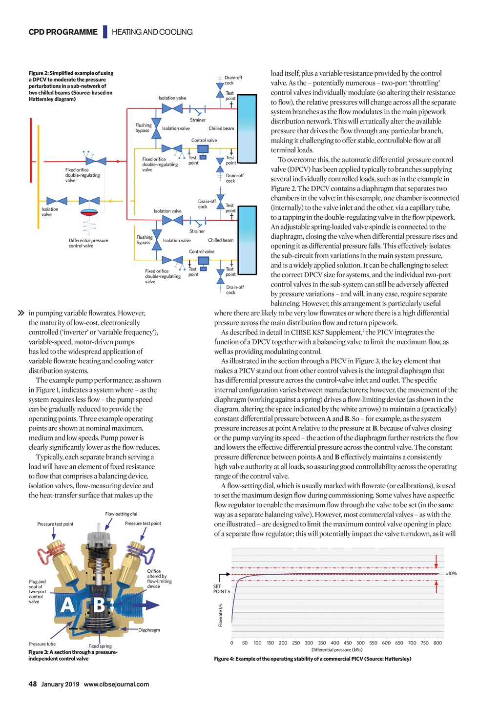


CPD PROGRAMME | HEATING AND COOLING load itself, plus a variable resistance provided by the control valve. As the potentially numerous two-port throttling Test control valves individually modulate (so altering their resistance Isolation valve point to flow), the relative pressures will change across all the separate system branches as the flow modulates in the main pipework Strainer distribution network. This will erratically alter the available Flushing Chilled beam Isolation valve bypass pressure that drives the flow through any particular branch, Control valve making it challenging to offer stable, controllable flow at all terminal loads. Test Test Fixed orifice To overcome this, the automatic differential pressure control point point double-regulatiing valve Fixed orifice valve (DPCV) has been applied typically to branches supplying double-regulating Drain-off several individually controlled loads, such as in the example in valve cock Figure 2. The DPCV contains a diaphragm that separates two chambers in the valve; in this example, one chamber is connected Drain-off Test cock (internally) to the valve inlet and the other, via a capillary tube, Isolation point Isolation valve valve to a tapping in the double-regulating valve in the flow pipework. An adjustable spring-loaded valve spindle is connected to the Strainer diaphragm, closing the valve when differential pressure rises and Flushing Chilled beam Differential pressure Isolation valve bypass control valve opening it as differential pressure falls. This effectively isolates Control valve the sub-circuit from variations in the main system pressure, and is a widely applied solution. It can be challenging to select Test Test Fixed orifice point point the correct DPCV size for systems, and the individual two-port double-regulatiing valve control valves in the sub-system can still be adversely affected Drain-off cock by pressure variations and will, in any case, require separate balancing. However, this arrangement is particularly useful in pumping variable flowrates. However, where there are likely to be very low flowrates or where there is a high differential thematurity of low-cost, electronically pressure across the main distribution flow and return pipework. controlled (inverter or variable frequency), As described in detail in CIBSE KS7 Supplement,2 the PICV integrates the function of a DPCV together with a balancing valve to limit the maximum flow, as variable-speed, motor-driven pumps well as providing modulating control. has led to the widespread application of As illustrated in the section through a PICV in Figure 3, the key element that variable flowrate heating and cooling water makes a PICV stand out from other control valves is the integral diaphragm that distribution systems. has differential pressure across the control-valve inlet and outlet. The specific The example pump performance, as shown internal configuration varies between manufacturers; however, the movement of the in Figure 1, indicates a system where as the diaphragm (working against a spring) drives a flow-limiting device (as shown in the system requires less flow the pump speed diagram, altering the space indicated by the white arrows) to maintain a (practically) can be gradually reduced to provide the constant differential pressure between A and B. So for example, as the system operating points. Three example operating pressure increases at point A relative to the pressure at B, because of valves closing points are shown at nominal maximum, or the pump varying its speed the action of the diaphragm further restricts the flow medium and low speeds. Pump power is and lowers the effective differential pressure across the control valve. The constant clearly significantly lower as the flow reduces. pressure difference between points A and B effectively maintains a consistently Typically, each separate branch serving a high valve authority at all loads, so assuring good controllability across the operating load will have an element of fixed resistance range of the control valve. to flow that comprises a balancing device, A flow-setting dial, which is usually marked with flowrate (or calibrations), is used isolation valves, flow-measuring device and to set the maximum design flow during commissioning. Some valves have a specific the heat-transfer surface that makes up the flow regulator to enable the maximum flow through the valve to be set (in the same Flow-setting dial way as a separate balancing valve). However, most commercial valves as with the Pressure test point Pressure test point one illustrated are designed to limit the maximum control valve opening in place of a separate flow regulator; this will potentially impact the valve turndown, as it will Figure 2: Simplified example of using a DPCV to moderate the pressure perturbations in a sub-network of two chilled beams (Source: based on Hattersley diagram) Orifice altered by flow-limiting device A B 10% SET POINT 5 Flowrate I/s Plug and seat of two-port control valve Drain-off cock Diaphragm Pressure tube Fixed spring Figure 3: A section through a pressureindependent control valve 0 50 100 150 200 250 300 350 400 450 500 550 600 650 700 750 800 Differential pressure (kPa) Figure 4: Example of the operating stability of a commercial PICV (Source: Hattersley) 48 January 2019 www.cibsejournal.com CIBSE Jan19 pp47-50 CPD 4.indd 48 21/12/2018 15:13