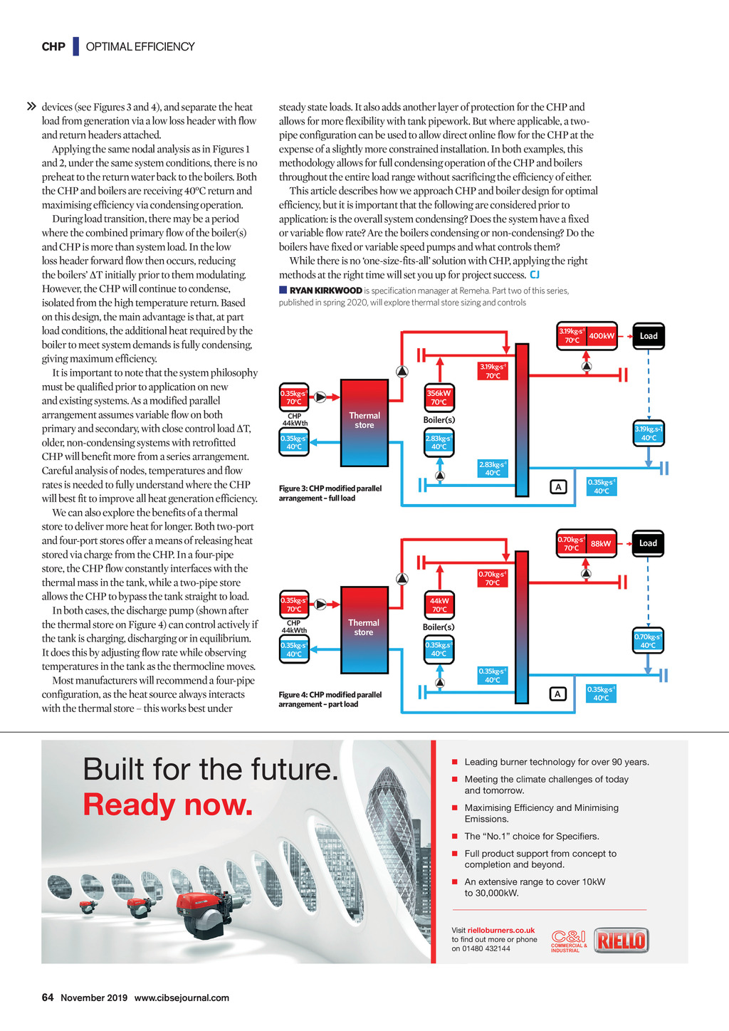

CHP | OPTIMAL EFFICIENCY devices (see Figures 3 and 4), and separate the heat load from generation via a low loss header with flow and return headers attached. Applying the same nodal analysis as in Figures 1 and 2, under the same system conditions, there is no preheat to the return water back to the boilers. Both the CHP and boilers are receiving 40C return and maximising efficiency via condensing operation. During load transition, there may be a period where the combined primary flow of the boiler(s) and CHP is more than system load. In the low loss header forward flow then occurs, reducing the boilers T initially prior to them modulating. However, the CHP will continue to condense, isolated from the high temperature return. Based on this design, the main advantage is that, at part load conditions, the additional heat required by the boiler to meet system demands is fully condensing, giving maximum efficiency. It is important to note that the system philosophy must be qualified prior to application on new and existing systems. As a modified parallel arrangement assumes variable flow on both primary and secondary, with close control load T, older, non-condensing systems with retrofitted CHP will benefit more from a series arrangement. Careful analysis of nodes, temperatures and flow rates is needed to fully understand where the CHP will best fit to improve all heat generation efficiency. We can also explore the benefits of a thermal store to deliver more heat for longer. Both two-port and four-port stores offer a means of releasing heat stored via charge from the CHP. In a four-pipe store, the CHP flow constantly interfaces with the thermal mass in the tank, while a two-pipe store allows the CHP to bypass the tank straight to load. In both cases, the discharge pump (shown after the thermal store on Figure 4) can control actively if the tank is charging, discharging or in equilibrium. It does this by adjusting flow rate while observing temperatures in the tank as the thermocline moves. Most manufacturers will recommend a four-pipe configuration, as the heat source always interacts with the thermal store this works best under steady state loads. It also adds another layer of protection for the CHP and allows for more flexibility with tank pipework. But where applicable, a twopipe configuration can be used to allow direct online flow for the CHP at the expense of a slightly more constrained installation. In both examples, this methodology allows for full condensing operation of the CHP and boilers throughout the entire load range without sacrificing the efficiency of either. This article describes how we approach CHP and boiler design for optimal efficiency, but it is important that the following are considered prior to application: is the overall system condensing? Does the system have a fixed or variable flow rate? Are the boilers condensing or non-condensing? Do the boilers have fixed or variable speed pumps and what controls them? While there is no one-size-fits-all solution with CHP, applying the right methods at the right time will set you up for project success. CJ RYAN KIRKWOOD is specification manager at Remeha. Part two of this series, published in spring 2020, will explore thermal store sizing and controls 3.19kg.s-1 400kW 70oC Load 3.19kg.s-1 70oC 0.35kg.s-1 70oC 356kW 70oC Thermal store CHP 44kWth 0.35kg.s-1 40oC Boiler(s) 3.19kg.s-1 40oC 2.83kg.s-1 40oC 2.83kg.s-1 40oC A Figure 3: CHP modified parallel arrangement full load 0.35kg.s-1 40oC 0.70kg.s-1 88kW 70oC Load 0.70kg.s-1 70oC 0.35kg.s-1 70oC CHP 44kWth 44kW 70oC Thermal store 0.35kg.s-1 40oC Boiler(s) 0.70kg.s-1 40oC 0.35kg.s-1 40oC 0.35kg.s-1 40oC A Figure 4: CHP modified parallel arrangement part load )\PS[MVY[OLM\[\YL 9LHK`UV^ 0.35kg.s-1 40oC 9 3LHKPUNI\YULY[LJOUVSVN`MVYV]LY `LHYZ 9 4LL[PUN[OLJSPTH[LJOHSSLUNLZVM[VKH` HUK[VTVYYV^ 9 4H_PTPZPUN,MJPLUJ`HUK4PUPTPZPUN ,TPZZPVUZ 9 ;OL5VJOVPJLMVY:WLJPLYZ 9 -\SSWYVK\J[Z\WWVY[MYVTJVUJLW[[V JVTWSL[PVUHUKIL`VUK 9 (UL_[LUZP]LYHUNL[VJV]LYR> [VR> =PZP[YPLSSVI\YULYZJV\R [VUKV\[TVYLVYWOVUL VU COMMERCIAL & INDUSTRIAL 64 November 2019 www.cibsejournal.com CIBSE Nov19 pp63-64 Rehema.indd 64 25/10/2019 18:07