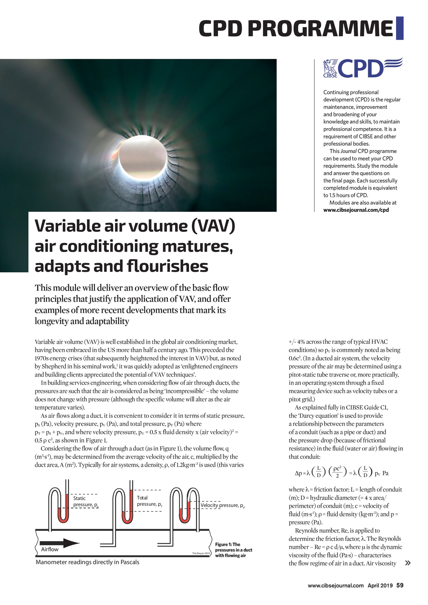

SPONSOR CPD PROGRAMME Continuing professional development (CPD) is the regular maintenance, improvement and broadening of your knowledge and skills, to maintain professional competence. It is a requirement of CIBSE and other professional bodies. This Journal CPD programme can be used to meet your CPD requirements. Study the module and answer the questions on the final page. Each successfully completed module is equivalent to 1.5 hours of CPD. Modules are also available at www.cibsejournal.com/cpd Variable air volume (VAV) air conditioning matures, adapts and flourishes This module will deliver an overview of the basic flow principles that justify the application of VAV, and offer examples of more recent developments that mark its longevity and adaptability Variable air volume (VAV) is well established in the global air conditioning market, having been embraced in the US more than half a century ago. This preceded the 1970s energy crises (that subsequently heightened the interest in VAV) but, as noted by Shepherd in his seminal work,1 it was quickly adopted as enlightened engineers and building clients appreciated the potential of VAV techniques. In building services engineering, when considering flow of air through ducts, the pressures are such that the air is considered as being incompressible the volume does not change with pressure (although the specific volume will alter as the air temperature varies). As air flows along a duct, it is convenient to consider it in terms of static pressure, pS (Pa), velocity pressure, pV (Pa), and total pressure, pT (Pa) where pT = pS + pV, and where velocity pressure, pV = 0.5 x fluid density x (air velocity)2 = 0.5 c2, as shown in Figure 1. Considering the flow of air through a duct (as in Figure 1), the volume flow, q (m3.s-1), may be determined from the average velocity of the air, c, multiplied by the duct area, A (m2). Typically for air systems, a density, , of 1.2kg.m-3 is used (this varies +/- 4% across the range of typical HVAC conditions) so pV is commonly noted as being 0.6c2. (In a ducted air system, the velocity pressure of the air may be determined using a pitot-static tube traverse or, more practically, in an operating system through a fixed measuring device such as velocity tubes or a pitot grid.) As explained fully in CIBSE Guide C1, the Darcy equation is used to provide a relationship between the parameters of a conduit (such as a pipe or duct) and the pressure drop (because of frictional resistance) in the fluid (water or air) flowing in that conduit: Static pressure, pS Total pressure, pT Velocity pressure, pV Tim Dwyer 2019 Manometer readings directly in Pascals Figure 1: The pressures in a duct with flowing air ( DL ) ( c2 ) = ( DL ) p 2 p = V Pa where = friction factor; L = length of conduit (m); D = hydraulic diameter (= 4 x area/ perimeter) of conduit (m); c = velocity of fluid (m.s-1); = fluid density (kg.m-3); and p = pressure (Pa). Reynolds number, Re, is applied to determine the friction factor, . The Reynolds number Re = c d/, where is the dynamic viscosity of the fluid (Pa.s) characterises the flow regime of air in a duct. Air viscosity www.cibsejournal.com April 2019 59 CIBSE Apr19 pp60-62 CPD v2.indd 59 22/03/2019 17:05