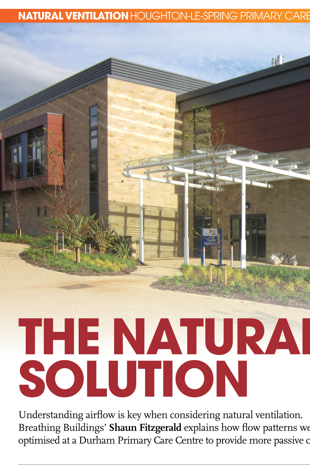
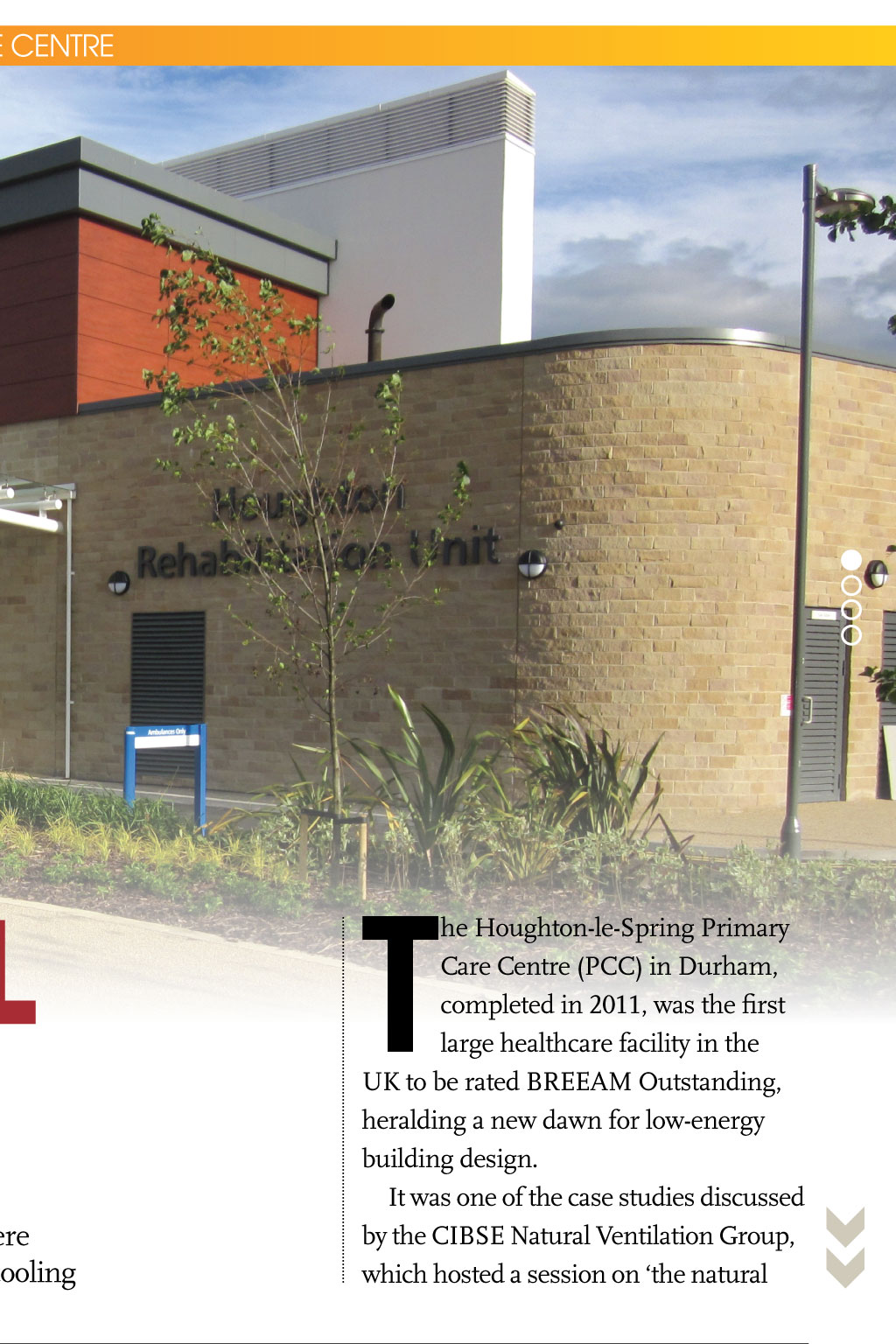
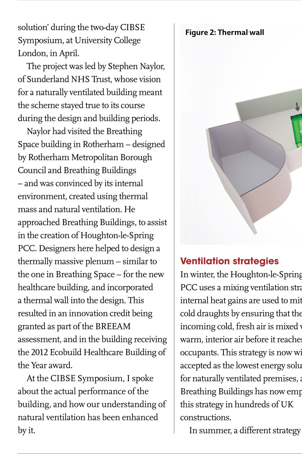
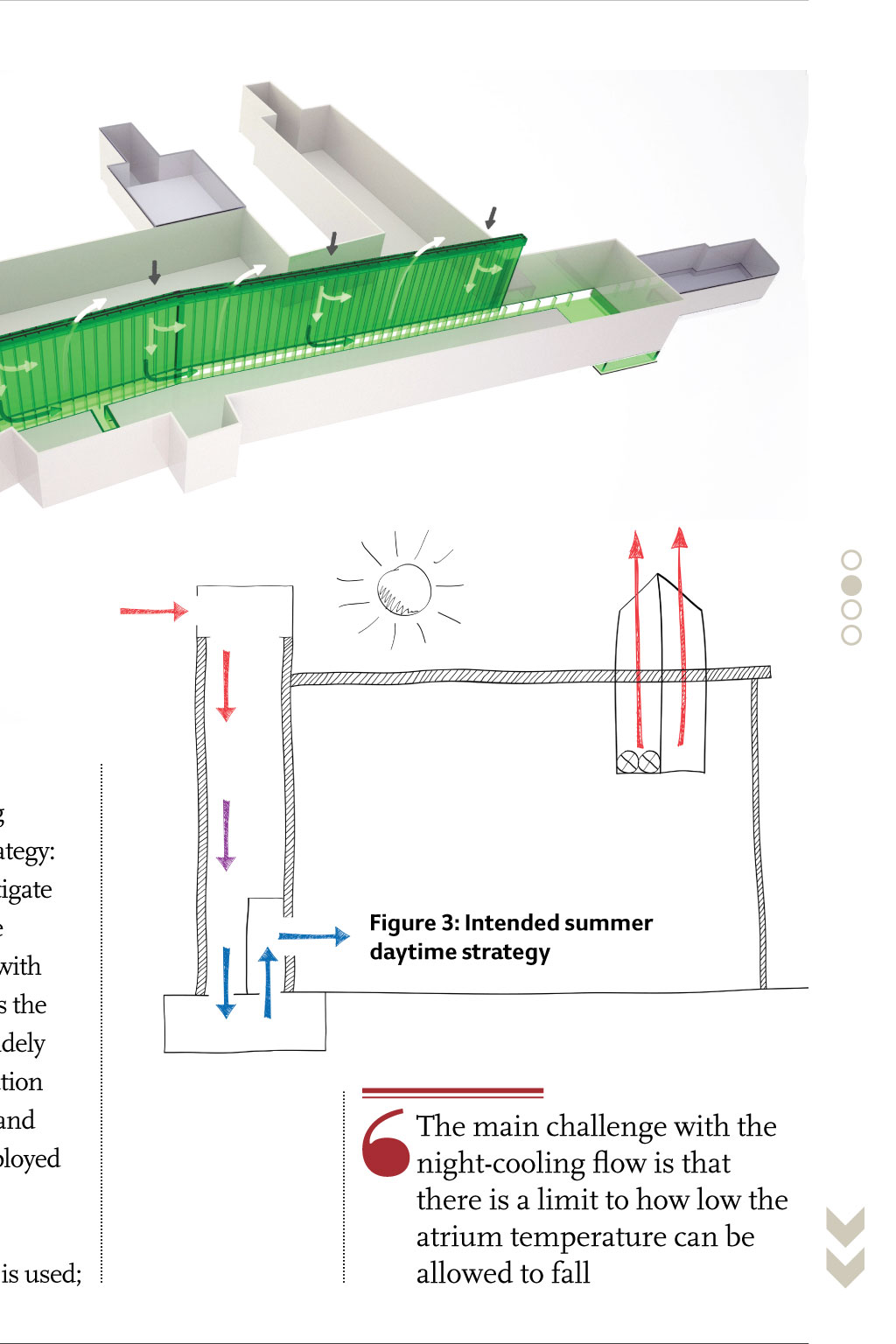
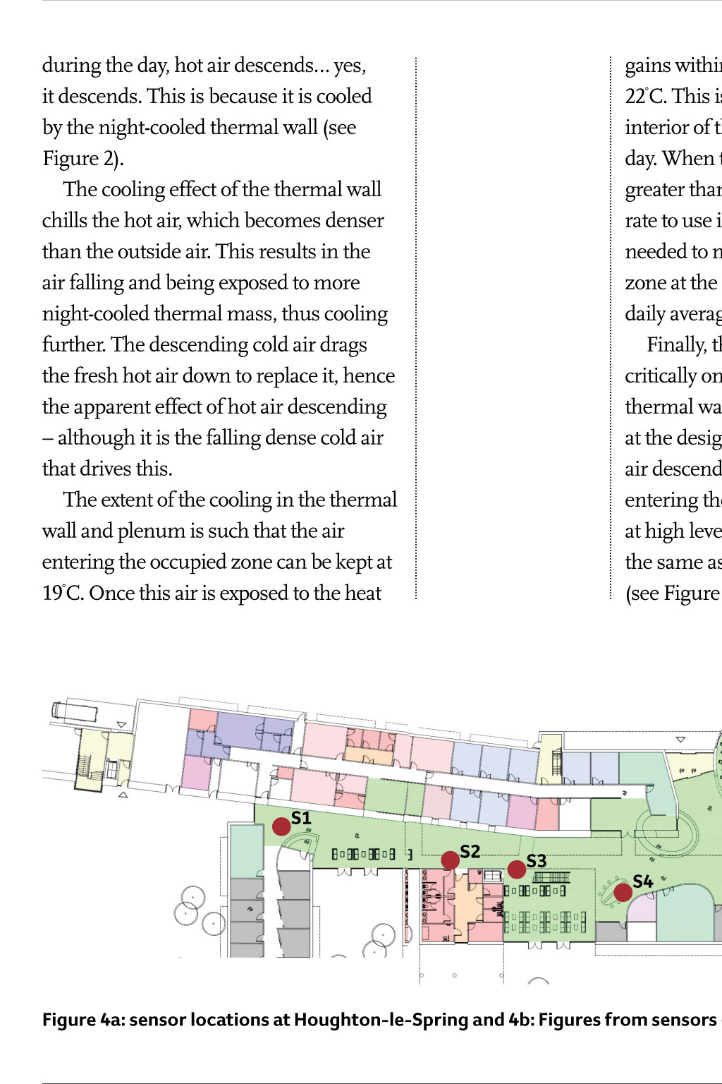
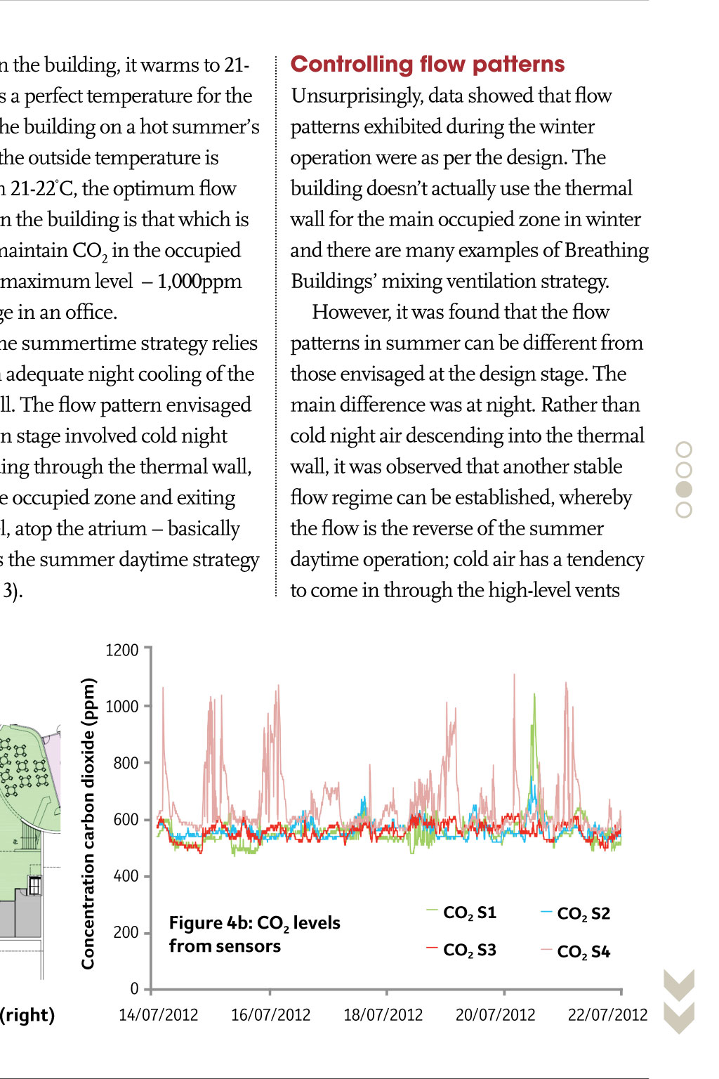
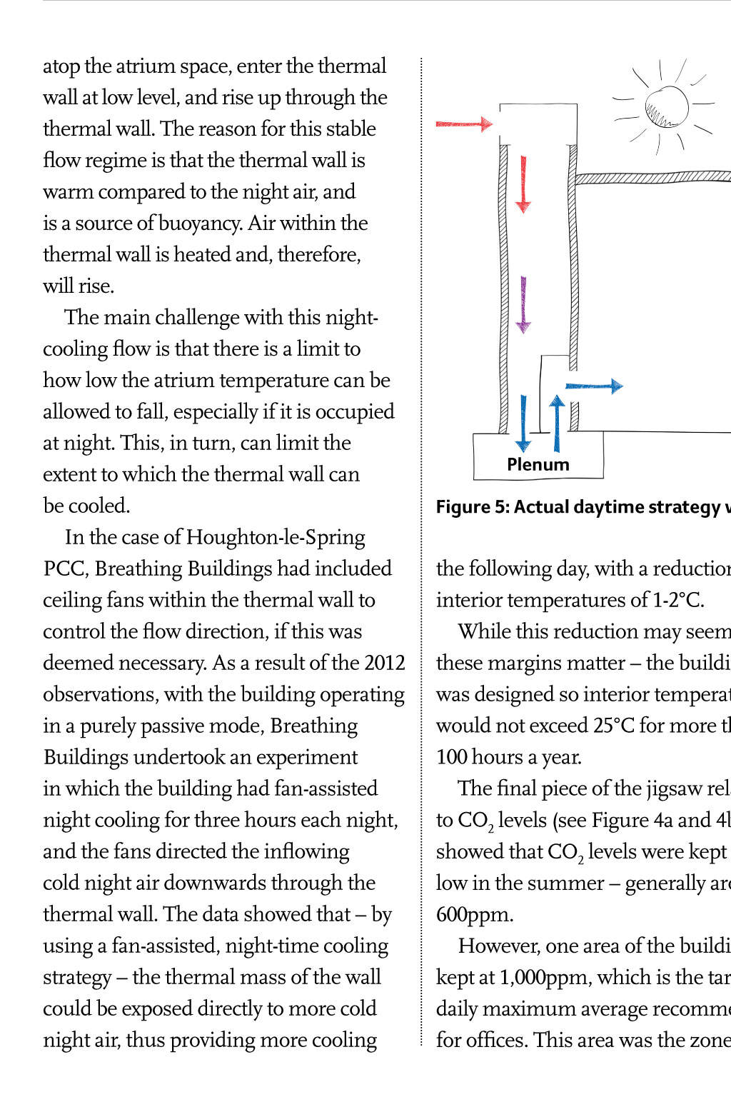

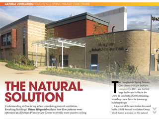
nAtuRAL VentiLAtion houghToN-lE-sprINg prIMary carE cENTrE T the nAtuRAL soLution he Houghton-le-Spring Primary Care Centre (PCC) in Durham, completed in 2011, was the first large healthcare facility in the UK to be rated BREEAM Outstanding, heralding a new dawn for low-energy building design. It was one of the case studies discussed by the CIBSE Natural Ventilation Group, which hosted a session on the natural Understanding airflow is key when considering natural ventilation. Breathing Buildings Shaun Fitzgerald explains how flow patterns were optimised at a Durham Primary Care Centre to provide more passive cooling solution during the two-day CIBSE Symposium, at University College London, in April. The project was led by Stephen Naylor, of Sunderland NHS Trust, whose vision for a naturally ventilated building meant the scheme stayed true to its course during the design and building periods. Naylor had visited the Breathing Space building in Rotherham designed by Rotherham Metropolitan Borough Council and Breathing Buildings and was convinced by its internal environment, created using thermal mass and natural ventilation. He approached Breathing Buildings, to assist in the creation of Houghton-le-Spring PCC. Designers here helped to design a thermally massive plenum similar to the one in Breathing Space for the new healthcare building, and incorporated a thermal wall into the design. This resulted in an innovation credit being granted as part of the BREEAM assessment, and in the building receiving the 2012 Ecobuild Healthcare Building of the Year award. At the CIBSE Symposium, I spoke about the actual performance of the building, and how our understanding of natural ventilation has been enhanced by it. Figure 2: thermal wall Ventilation strategies In winter, the Houghton-le-Spring PCC uses a mixing ventilation strategy: internal heat gains are used to mitigate cold draughts by ensuring that the incoming cold, fresh air is mixed with warm, interior air before it reaches the occupants. This strategy is now widely accepted as the lowest energy solution for naturally ventilated premises, and Breathing Buildings has now employed this strategy in hundreds of UK constructions. In summer, a different strategy is used; during the day, hot air descends yes, it descends. This is because it is cooled by the night-cooled thermal wall (see Figure 2). The cooling effect of the thermal wall chills the hot air, which becomes denser than the outside air. This results in the air falling and being exposed to more night-cooled thermal mass, thus cooling further. The descending cold air drags the fresh hot air down to replace it, hence the apparent effect of hot air descending although it is the falling dense cold air that drives this. The extent of the cooling in the thermal wall and plenum is such that the air entering the occupied zone can be kept at 19C. Once this air is exposed to the heat Figure 3: intended summer daytime strategy The main challenge with the night-cooling flow is that there is a limit to how low the atrium temperature can be allowed to fall gains within the building, it warms to 2122C. This is a perfect temperature for the interior of the building on a hot summers day. When the outside temperature is greater than 21-22C, the optimum flow rate to use in the building is that which is needed to maintain CO2 in the occupied zone at the maximum level 1,000ppm daily average in an office. Finally, the summertime strategy relies critically on adequate night cooling of the thermal wall. The flow pattern envisaged at the design stage involved cold night air descending through the thermal wall, entering the occupied zone and exiting at high level, atop the atrium basically the same as the summer daytime strategy (see Figure 3). controlling flow patterns Unsurprisingly, data showed that flow patterns exhibited during the winter operation were as per the design. The building doesnt actually use the thermal wall for the main occupied zone in winter and there are many examples of Breathing Buildings mixing ventilation strategy. However, it was found that the flow patterns in summer can be different from those envisaged at the design stage. The main difference was at night. Rather than cold night air descending into the thermal wall, it was observed that another stable flow regime can be established, whereby the flow is the reverse of the summer daytime operation; cold air has a tendency to come in through the high-level vents S1 S2 S3 S4 Concentration carbon dioxide (ppm) 1200 1000 800 600 400 200 CO2 S1 CO2 S2 CO2 S3 Figure 4b: CO2 levels from sensors CO2 S4 0 Figure 4a: sensor locations at Houghton-le-Spring and 4b: Figures from sensors (right) atop the atrium space, enter the thermal wall at low level, and rise up through the thermal wall. The reason for this stable flow regime is that the thermal wall is warm compared to the night air, and is a source of buoyancy. Air within the thermal wall is heated and, therefore, will rise. The main challenge with this nightcooling flow is that there is a limit to how low the atrium temperature can be allowed to fall, especially if it is occupied at night. This, in turn, can limit the extent to which the thermal wall can be cooled. In the case of Houghton-le-Spring PCC, Breathing Buildings had included ceiling fans within the thermal wall to control the flow direction, if this was deemed necessary. As a result of the 2012 observations, with the building operating in a purely passive mode, Breathing Buildings undertook an experiment in which the building had fan-assisted night cooling for three hours each night, and the fans directed the inflowing cold night air downwards through the thermal wall. The data showed that by using a fan-assisted, night-time cooling strategy the thermal mass of the wall could be exposed directly to more cold night air, thus providing more cooling 14/07/2012 16/07/2012 BE parT of ThE 2016 TEchNIcal syMposIuM The CIBSE Technical Symposium committee is looking for papers, posters or case studies for the 2016 event. For more information, see this months CiBSe news. Plenum Figure 5: actual daytime strategy with an open front entrance the following day, with a reduction in interior temperatures of 1-2C. While this reduction may seem small, these margins matter the building was designed so interior temperatures would not exceed 25C for more than 100 hours a year. The final piece of the jigsaw related to CO2 levels (see Figure 4a and 4b). We showed that CO2 levels were kept very low in the summer generally around 600ppm. However, one area of the building was kept at 1,000ppm, which is the target daily maximum average recommended for offices. This area was the zone eor RMadE BE parT of ThE 2016 TEchNIcal syMposIuM 18/07/2012 20/07/2012 22/07/2012 closest to the main entrance and it is perhaps a surprising find because areas in the vicinity of opening doors are normally exposed to more fresh air. The exact reasons for the slightly elevated CO2 levels near the door are unknown, because the pattern of occupancy and dwell time within the different parts of the waiting area were not monitored. However, it is possible that if the building has an open door, is cooler inside than outside, and air is supplied at the centre, then fresher conditions would be expected near the thermal wall, and higher CO2 levels near the point of exit. Also an open door would be an exit for the stale air if it is cooler than outside (see Figure 5). Lessons learned The study showed that the building performs extremely well and that the passive cooling, resulting from the thermal mass, provides a significant and beneficial thermal buffer in summer. However, the actual operation of the building led to differences in flow patterns from those envisaged at the design stage, although with the appropriate location of sensors and control strategy it was shown that the systems can still work extremely well. cJ