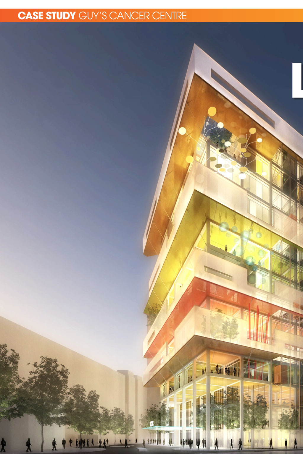
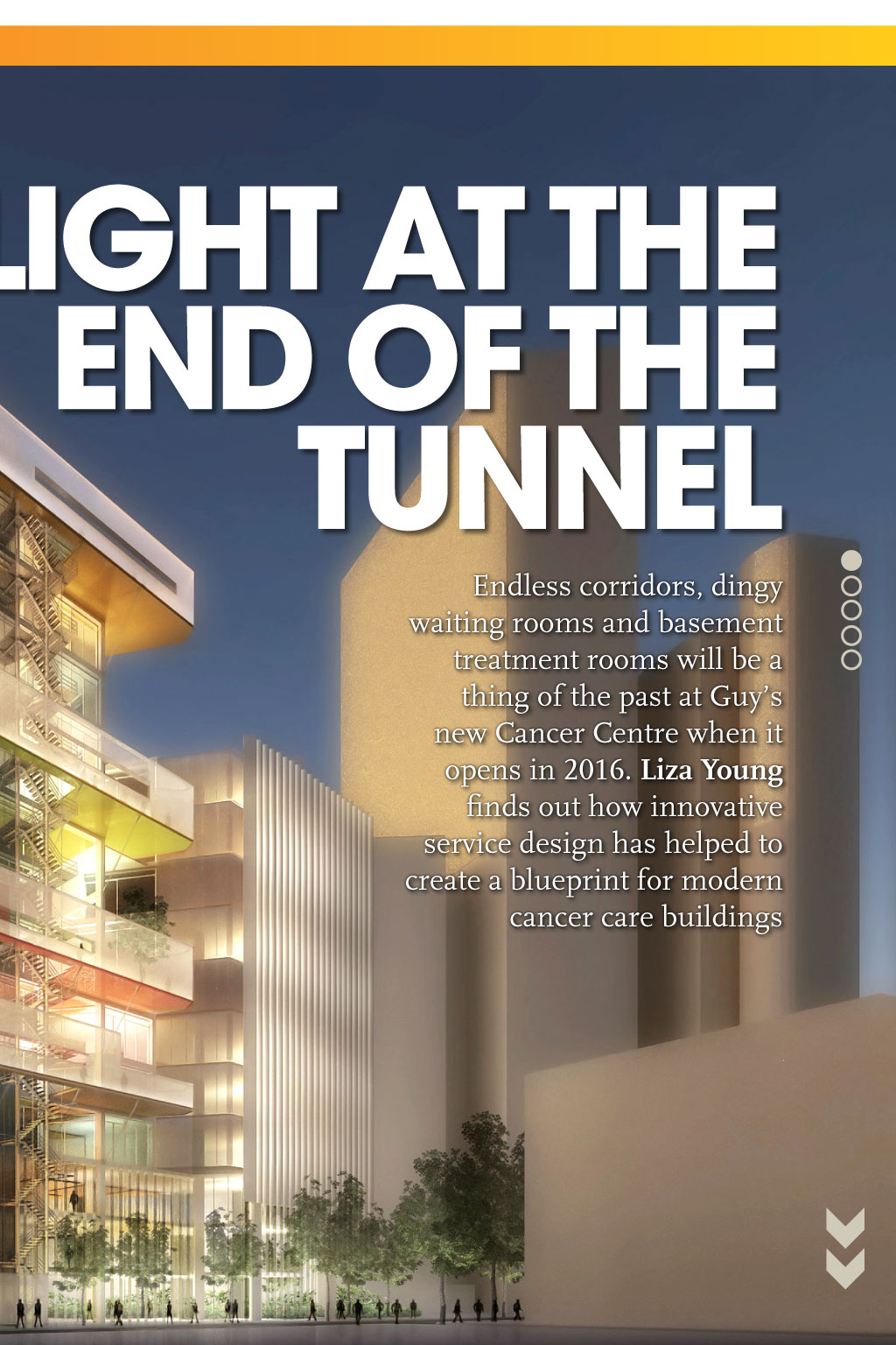

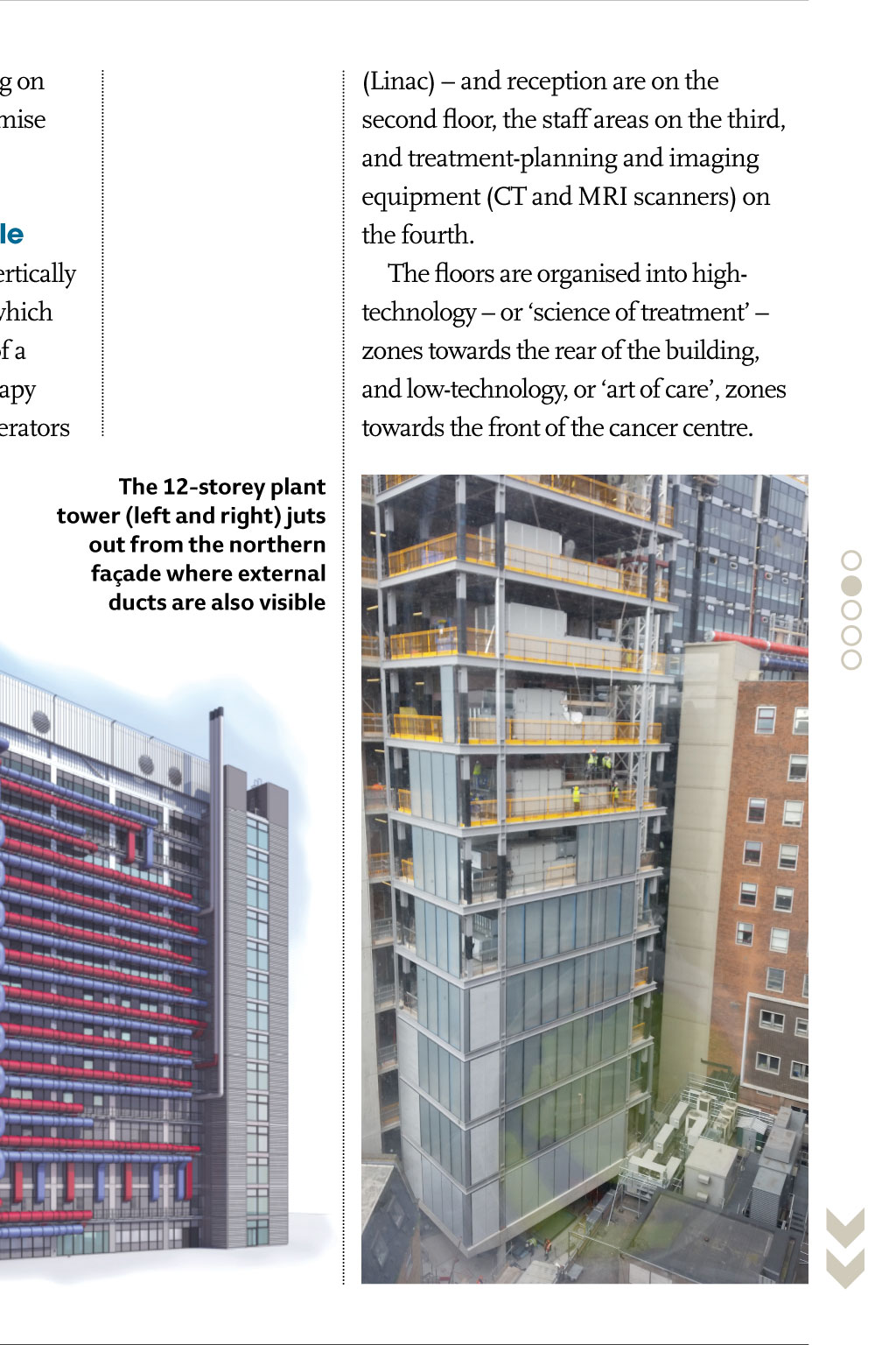
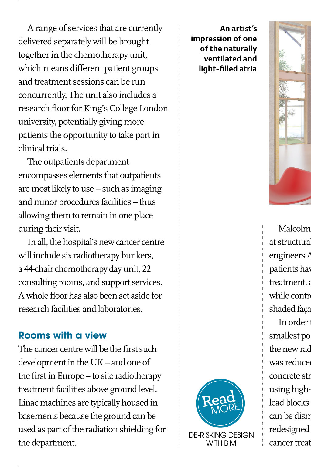
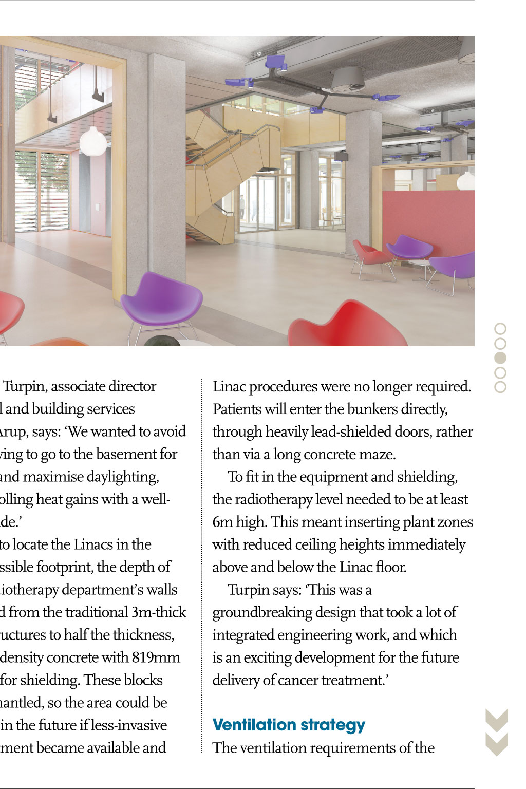
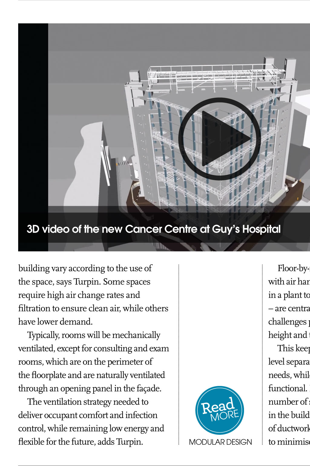
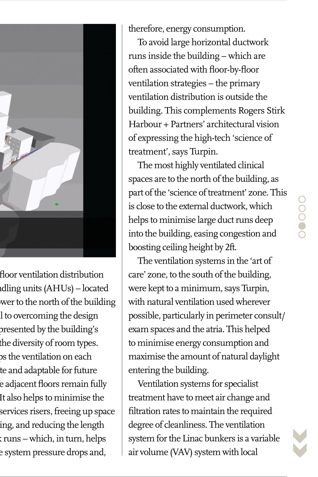


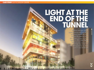
cAse stuDy guys caNcEr cENTrE Light At the enD of the tunneL projEcT TEaM Client: Guys and St Thomas NHS Foundation Trust Build project manager: Essentia Main contractor: Laing ORourke architects: Rogers Stirk Harbour + Partners and Stantec Structural and building services engineers: Arup academic partner: Kings College London L ong hospital corridors: disorientating, oppressive, intimidating. It is a journey that cancer patients are familiar with traipsing along endless passageways between consultants rooms, chemotherapy wards and radiotherapy departments. The latter are particularly depressing, involving descents into remote basements illuminated by harsh artificial light. The days of navigating endless corridors will be a thing of the past at the new 160m Cancer Centre at Guys and St Thomas Hospital, which opens in autumn 2016. Lead architect Rogers Stirk Harbour + Partners has reduced the distances between departments on the 200,000ft2 site by grouping the functions of the building into manageable, multi-storey sections termed villages by the hospital. This means consulting rooms and treatment departments are close together. The radiotherapy bunkers typically found at basement level have been moved to the second floor, where patients can benefit from daylight while they await their treatment. The heavy radiation shielding on these rooms has required a massive reorganisation of the services and clever A range of services that are currently delivered separately will be brought together in the chemotherapy unit, which means different patient groups and treatment sessions can be run concurrently. The unit also includes a research floor for Kings College London university, potentially giving more patients the opportunity to take part in clinical trials. The outpatients department encompasses elements that outpatients are most likely to use such as imaging and minor procedures facilities thus allowing them to remain in one place during their visit. In all, the hospitals new cancer centre will include six radiotherapy bunkers, a 44-chair chemotherapy day unit, 22 consulting rooms, and support services. A whole floor has also been set aside for research facilities and laboratories. Rooms with a view The cancer centre will be the first such development in the UK and one of the first in Europe to site radiotherapy treatment facilities above ground level. Linac machines are typically housed in basements because the ground can be used as part of the radiation shielding for the department. Endless corridors, dingy waiting rooms and basement treatment rooms will be a thing of the past at Guys new Cancer Centre when it opens in 2016. Liza Young finds out how innovative service design has helped to create a blueprint for modern cancer care buildings structural design, including ducting on the outside of the building to maximise internal space. Designing at a human scale The radiotherapy department is vertically stacked over three levels, each of which corresponds to a particular stage of a patients treatment. The radiotherapy machines known as linear accelerators the 12-storey plant tower (left and right) juts out from the northern faade where external ducts are also visible an artists impression of one of the naturally ventilated and light-filled atria eor RMadE dE-rIskINg dEsIgN wITh BIM Malcolm Turpin, associate director at structural and building services engineers Arup, says: We wanted to avoid patients having to go to the basement for treatment, and maximise daylighting, while controlling heat gains with a wellshaded faade. In order to locate the Linacs in the smallest possible footprint, the depth of the new radiotherapy departments walls was reduced from the traditional 3m-thick concrete structures to half the thickness, using high-density concrete with 819mm lead blocks for shielding. These blocks can be dismantled, so the area could be redesigned in the future if less-invasive cancer treatment became available and 3D video of the new Cancer Centre at Guys Hospital building vary according to the use of the space, says Turpin. Some spaces require high air change rates and filtration to ensure clean air, while others have lower demand. Typically, rooms will be mechanically ventilated, except for consulting and exam rooms, which are on the perimeter of the floorplate and are naturally ventilated through an opening panel in the faade. The ventilation strategy needed to deliver occupant comfort and infection control, while remaining low energy and flexible for the future, adds Turpin. eadE RMor Modular dEsIgN Floor-by-floor ventilation distribution with air handling units (AHUs) located in a plant tower to the north of the building are central to overcoming the design challenges presented by the buildings height and the diversity of room types. This keeps the ventilation on each level separate and adaptable for future needs, while adjacent floors remain fully functional. It also helps to minimise the number of services risers, freeing up space in the building, and reducing the length of ductwork runs which, in turn, helps to minimise system pressure drops and, Linac procedures were no longer required. Patients will enter the bunkers directly, through heavily lead-shielded doors, rather than via a long concrete maze. To fit in the equipment and shielding, the radiotherapy level needed to be at least 6m high. This meant inserting plant zones with reduced ceiling heights immediately above and below the Linac floor. Turpin says: This was a groundbreaking design that took a lot of integrated engineering work, and which is an exciting development for the future delivery of cancer treatment. Ventilation strategy The ventilation requirements of the therefore, energy consumption. To avoid large horizontal ductwork runs inside the building which are often associated with floor-by-floor ventilation strategies the primary ventilation distribution is outside the building. This complements Rogers Stirk Harbour + Partners architectural vision of expressing the high-tech science of treatment, says Turpin. The most highly ventilated clinical spaces are to the north of the building, as part of the science of treatment zone. This is close to the external ductwork, which helps to minimise large duct runs deep into the building, easing congestion and boosting ceiling height by 2ft. The ventilation systems in the art of care zone, to the south of the building, were kept to a minimum, says Turpin, with natural ventilation used wherever possible, particularly in perimeter consult/ exam spaces and the atria. This helped to minimise energy consumption and maximise the amount of natural daylight entering the building. Ventilation systems for specialist treatment have to meet air change and filtration rates to maintain the required degree of cleanliness. The ventilation system for the Linac bunkers is a variable air volume (VAV) system with local BiM image of a portion of the services overlaid with the building structure temperature control to each bunker. The VAV system allows the air volume for each bunker to be altered from the bunker control rooms and set back when unused. The air volume required depends on the treatment cycle, and a boost function can be used in one bunker at a time to purge contaminated air generated during the most intensive treatment cycles. heating and cooling The cancer centre has an array of room types, ranging from specialist imaging rooms requiring accurate temperature control and equipment and server rooms with high heat-load densities, to threestorey atria and consultation/exam rooms. Turpin says the heating and cooling terminal units are selected to suit the different requirements of these spaces, and include duct-mounted heating coils, radiant panels, underfloor heating, fan coil units and chilled beams. The aspiration with all these solutions was to minimise energy and provide appropriate levels of comfort, says Turpin. Chilled water for HVAC systems is generated from Turbocor chillers, and the Linac cooling is provided by free-cooling chillers, which have consistent year-round cooling load. (Linac) and reception are on the second floor, the staff areas on the third, and treatment-planning and imaging equipment (CT and MRI scanners) on the fourth. The floors are organised into hightechnology or science of treatment zones towards the rear of the building, and low-technology, or art of care, zones towards the front of the cancer centre. Heating is provided from a site-wide heating network, which includes a combined heat and power system. The space heating and cooling water systems are shared between floors, and can be isolated floor by floor as necessary, Turpin adds. eor RMadE projEcT TEaM the offsite solution Located in busy London Bridge, the cancer centres footprint reaches to the edges of its triangular site. As a result, layout and storage space were at a premium, making construction a logistical challenge. To overcome this, main contractor Laing ORourke used its design for manufacture and assembly (DfMA) processes to make parts in a factory for on-site assembly, thereby reducing in-situ building work. The Cancer Centre is targeted to achieve the BREEAM Healthcare Excellence rating, and aims to accommodate 700 outpatients at peak times. People were at the heart of the design, and patient feedback inspired the project team to come up with a novel solution that brought the radiotherapy units into the light and out of the basement which was also restricted because of a Roman boat buried 4m below the site! cJ Modular dEsIgN The 3,756 concrete elements that make up the buildings frame, and 1,080 unitised cladding panels that were fixed to the external faces, allowed the structure to grow at a rate of approximately one floor per week. The concrete wall on the southern elevation was built from five precast elements each weighing 11 tonnes with grouting between them the only work required on site. Both clinical and non-clinical services were tested in its factory before being delivered as a partly-modular system with ducts, cables and pipes pre-fitted in smart walls and prefabricated ceiling frames and connected on site. The 12-storey modularised steel plant tower, containing the AHUs for each level, was craned into place in five 4.2m-high sections. According to Laing ORourke, the DfMA approach will allow the project to be built 30% quicker than using conventional building methods. Turpin says: It took a while to refine the design to something this elegant and simple. The ideas evolved with the project, but the concept of modular construction was embedded in the project from the start. But its important to understand where [modular construction] may be an advantage, and where it may start to affect design negatively. Its about finding that balance. He this method is beneficial for quality control, site safety and speed of construction, because less work needs to be done onsite. The drawbacks could be increased cost although this is often balanced by reduction in programme (and costs associated with programme duration) and decreased ability to accommodate late changes. dE-rIskINg dEsIgN wITh BIM BIM Level 2 was used from day one on the project, enabling the team to change any fixtures and fittings where necessary and provide information for the hospitals facilities management team. On the project, separate models were federated in a Navisworks environment, and handed over to Laing ORourke at the end of the consultant design stages. Turpin says Navisworks allowed all the designers and the contractors models to be co-ordinated while each party retained control over their information. Turpin, says: We viewed BIM as an extension of the collaborative working that we are used to with architects and contractors. While we are still discovering the power of working in a BIM environment, we have already found that it is a great co-ordination aid, and can assist in the transfer of information between project parties. Project drawings were generated from the BIM models so there was consistency between the 3D BIM information and the 2D drawing sets. Turpin adds: The models helped to identify particular issues, especially where areas are heavily serviced and at risk of congestion. One advantage of BIM is that these issues were picked up in the design phase, de-risking the services installation.