

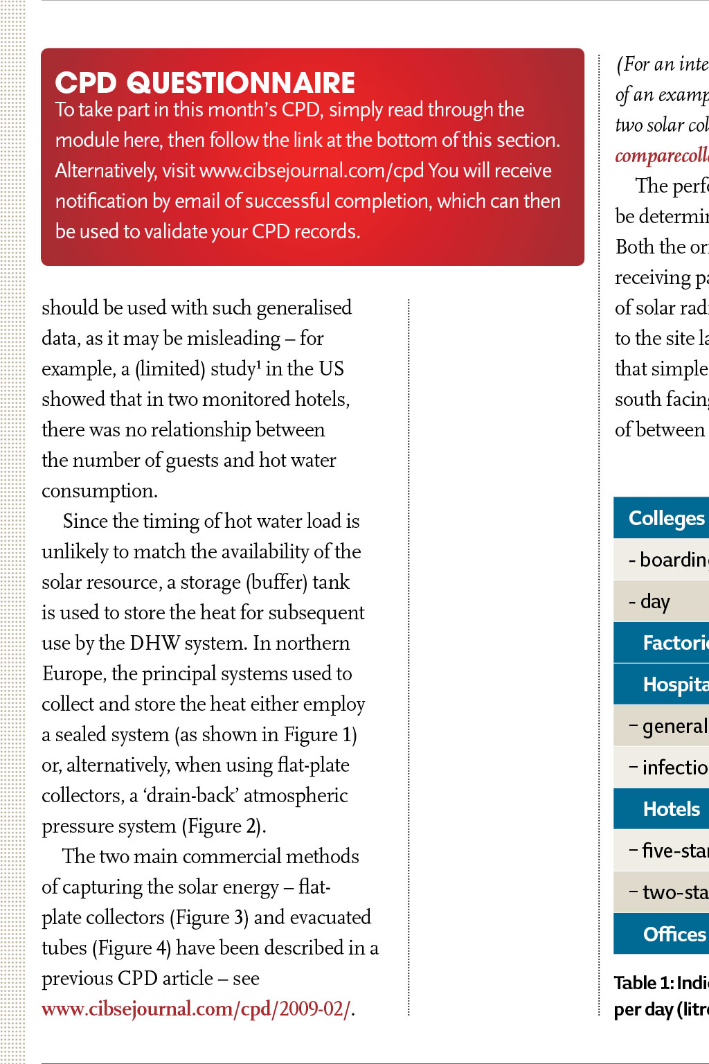
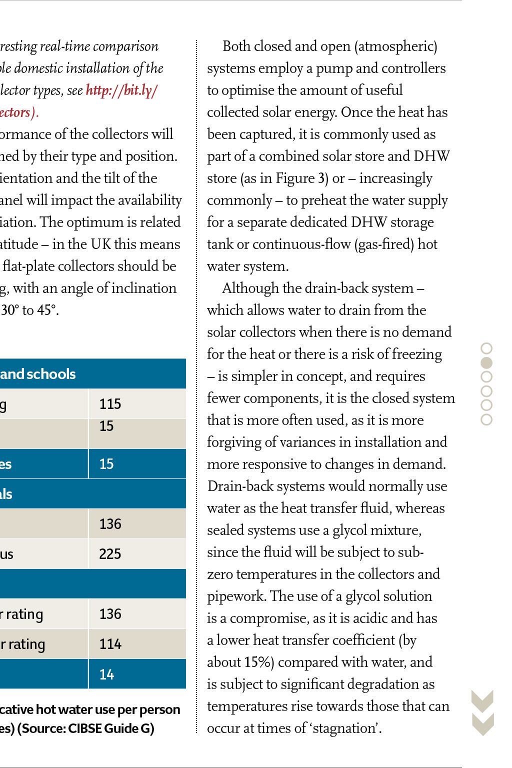
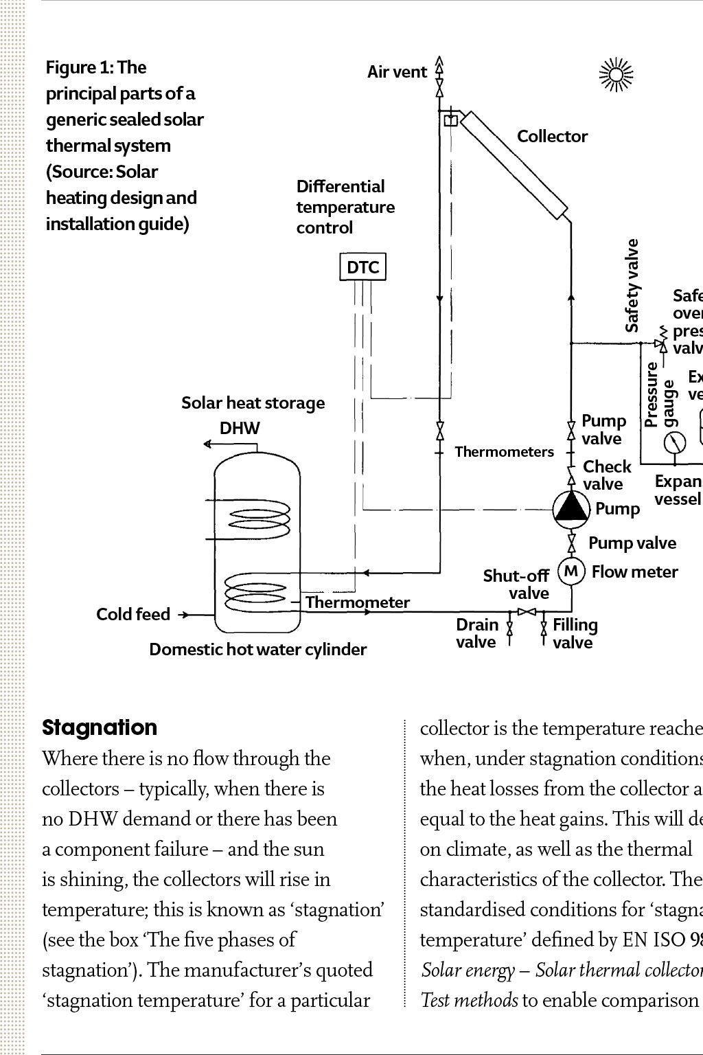
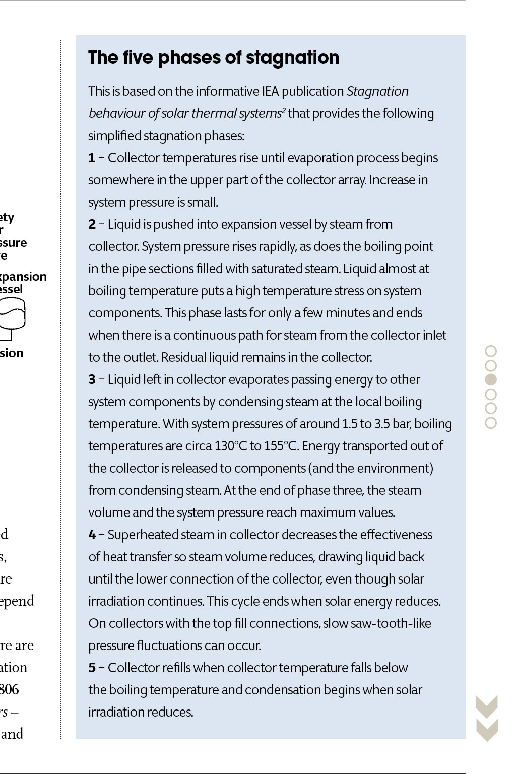
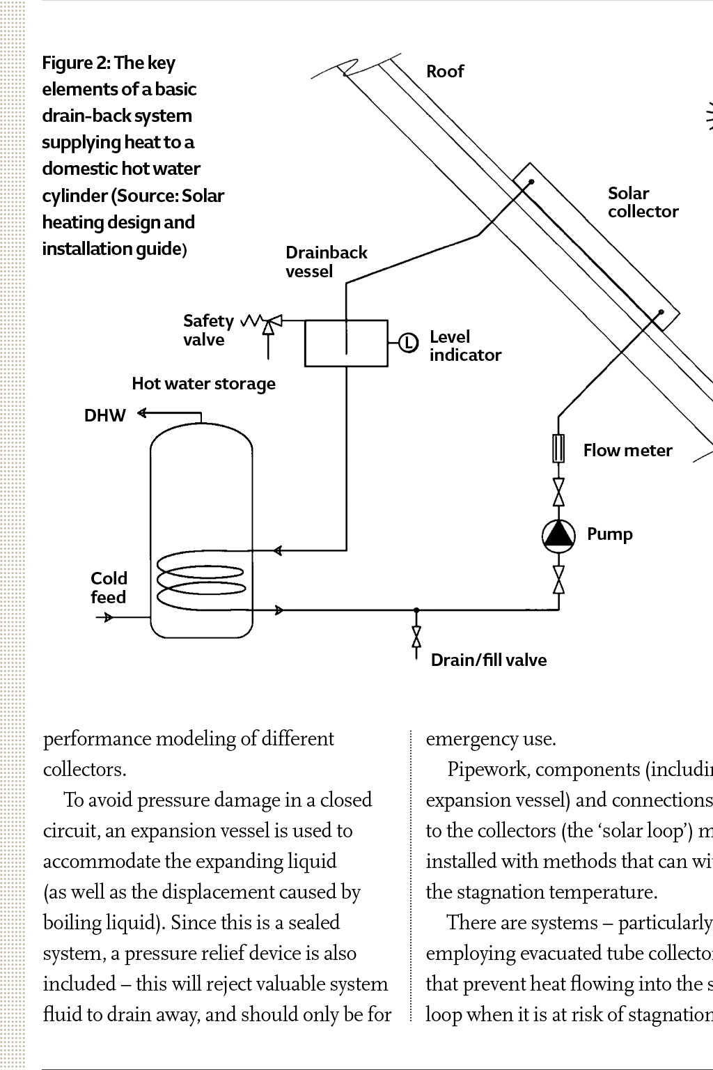
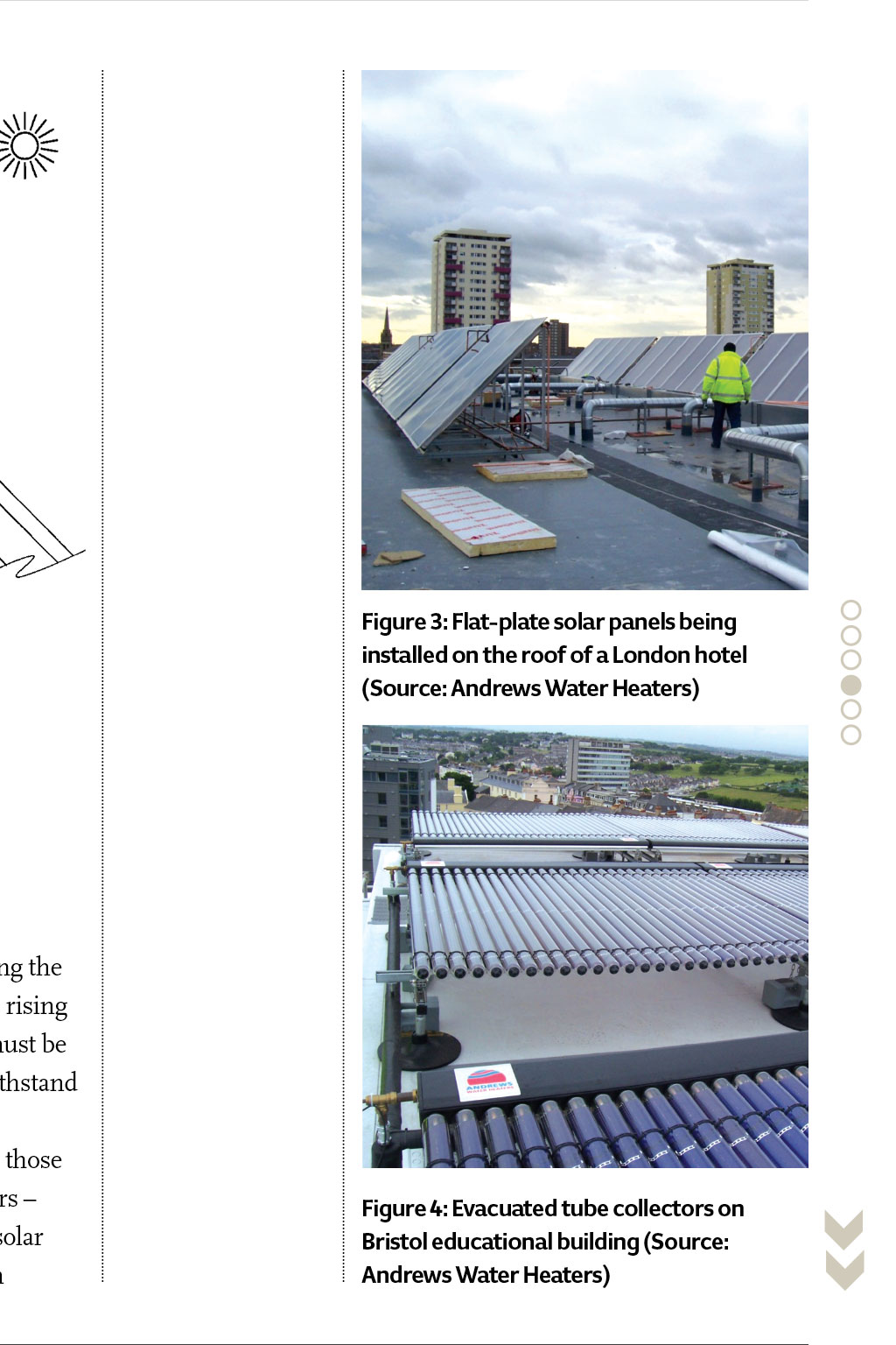
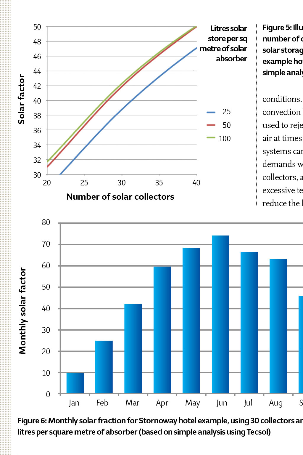
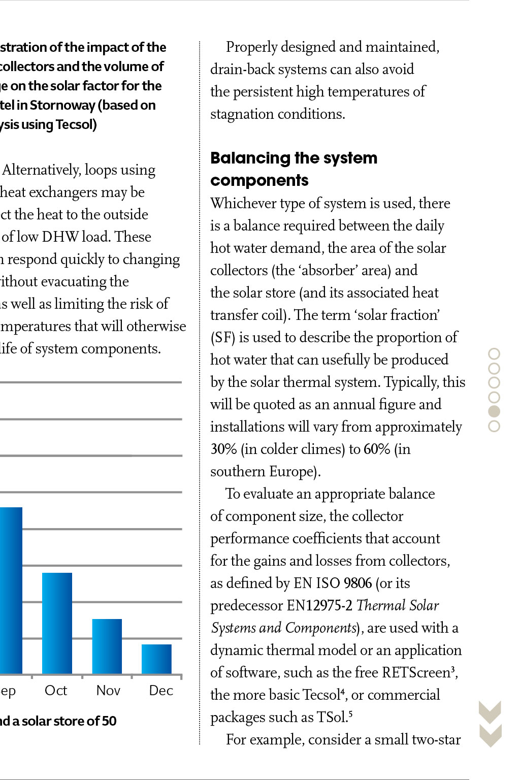
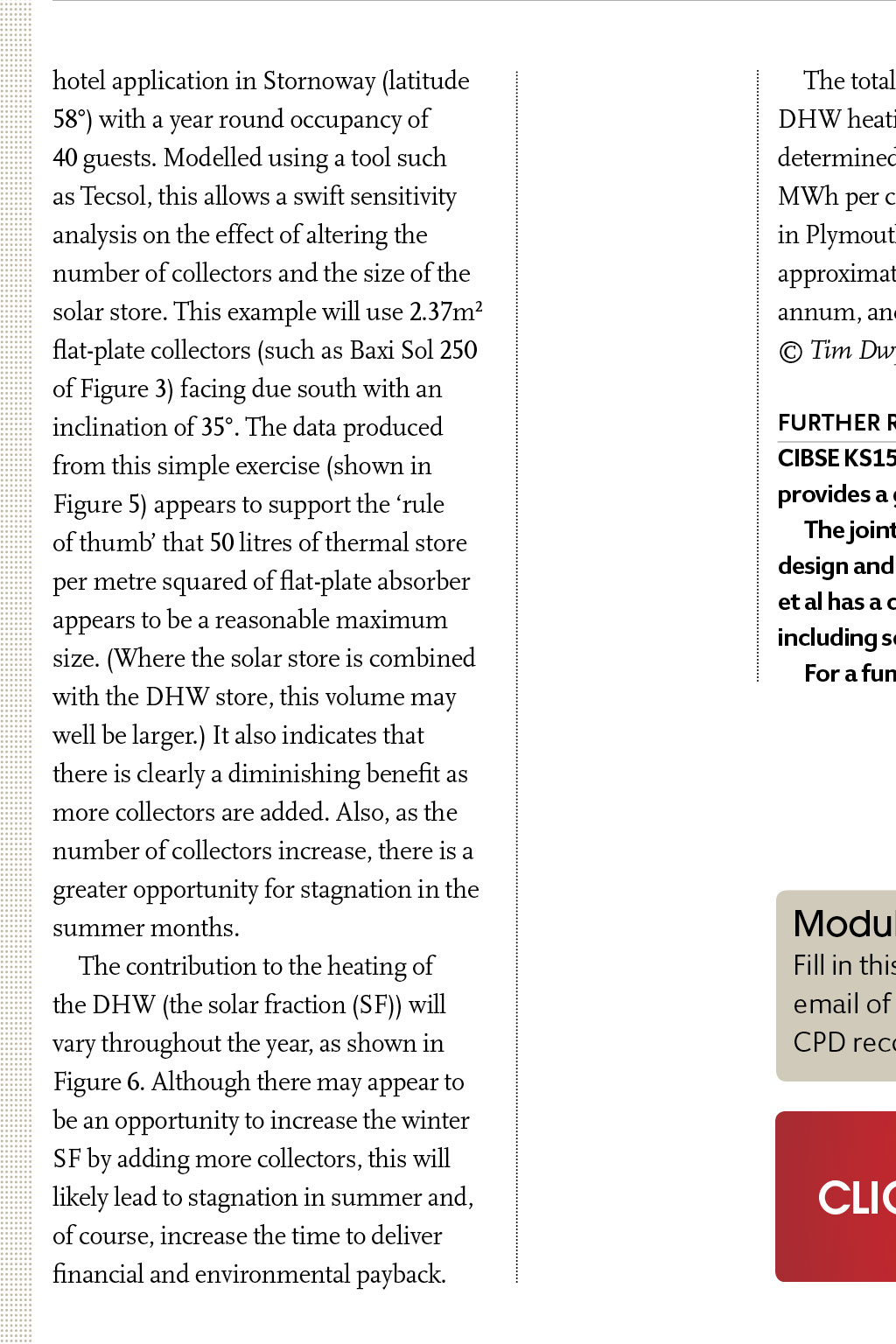


CPD PROGRAMME Professional development solar thermal heating for commercial potable hot water This CPD module considers appropriate sizing and stagnation mitigation for solar thermal systems used to supply heat for domestic (potable) hot water in commercial premises The CIBSE Journal CPD Programme Members of the Chartered Institution of Building Services Engineers (CIBSE) and other professional bodies are required to maintain their professional competence throughout their careers. There can be strong financial and environmental reasons to consider the application of solar thermal hot water heating in commercial applications. In the UK, the commercial Renewable Heat Incentive (RHI) payments provide around 10p per kWh of useful solar thermal heat generated to heat domestic hot water (DHW), in addition to the benefit of the no-cost hot water itself. The RHI is designed to provide a return on investment (ROI), so that properly applied technology is economically viable. It is particularly beneficial in applications where solar thermal is displacing oil or electric heating, and can give very attractive payback periods. Environmental assessment methods (such as BREEAM and LEED) recognise the contribution of applying renewable technologies either directly or by considering the low emission levels from the building heating systems. To ensure year round supply, (For an interesting real-time comparison of an example domestic installation of the two solar collector types, see http://bit.ly/ comparecollectors). The performance of the collectors will be determined by their type and position. Both the orientation and the tilt of the receiving panel will impact the availability of solar radiation. The optimum is related to the site latitude in the UK this means that simple flat-plate collectors should be south facing, with an angle of inclination of between 30 to 45. Continuing professional development (CPD) means the systematic maintenance, improvement and broadening of your knowledge and skills, and is therefore a longterm commitment to enhancing your competence. CPD is a requirement of both CIBSE and the Register of the Engineering Council (UK). CIBSE Journal is pleased to offer this module in its CPD programme. The programme is free and can be used by any reader. This module will help you to meet CIBSEs requirement for CPD. It will equally assist members of other institutions, who should record CPD activities in accordance with their institutions guidance. Simply study the module and complete the questionnaire on the final page, following the instructions for its submission. Modules will be available online at www.cibsejournal.com/cpd while the information they contain remains current. You can also complete the questionnaire online, and receive your results by return email. cPD QuestionnAiRe to take part in this months CPD, simply read through the module here, then follow the link at the bottom of this section. alternatively, visit www.cibsejournal.com/cpd you will receive notification by email of successful completion, which can then be used to validate your CPD records. should be used with such generalised data, as it may be misleading for example, a (limited) study1 in the US showed that in two monitored hotels, there was no relationship between the number of guests and hot water consumption. Since the timing of hot water load is unlikely to match the availability of the solar resource, a storage (buffer) tank is used to store the heat for subsequent use by the DHW system. In northern Europe, the principal systems used to collect and store the heat either employ a sealed system (as shown in Figure 1) or, alternatively, when using flat-plate collectors, a drain-back atmospheric pressure system (Figure 2). The two main commercial methods of capturing the solar energy flatplate collectors (Figure 3) and evacuated tubes (Figure 4) have been described in a previous CPD article see www.cibsejournal.com/cpd/2009-02/. Figure 1: the principal parts of a generic sealed solar thermal system (Source: Solar heating design and installation guide) solar thermal systems may be designed to work alongside and in conjunction with the majority of traditional hot water heating systems. Solar irradiance will vary throughout a day (and, of course, across the seasons) and depend on the weather it may range from tens of watts per square metre up to several hundred watts in the middle of a summer day, depending on the cloud cover. But even in northern European locations, there is sufficient solar energy to provide useful hot water typically meeting 30 to 40% of annual requirements in a commercial building application. To determine the most appropriate size of solar thermal system requires knowledge of the daily hot water consumption. Typically, this will relate to the type of installation, and can be evaluated using actual historic hot water usage data or tabulated data such as that shown in Table 1. However, some caution Both closed and open (atmospheric) systems employ a pump and controllers to optimise the amount of useful collected solar energy. Once the heat has been captured, it is commonly used as part of a combined solar store and DHW store (as in Figure 3) or increasingly commonly to preheat the water supply for a separate dedicated DHW storage tank or continuous-flow (gas-fired) hot water system. Although the drain-back system which allows water to drain from the solar collectors when there is no demand for the heat or there is a risk of freezing is simpler in concept, and requires fewer components, it is the closed system that is more often used, as it is more forgiving of variances in installation and more responsive to changes in demand. Drain-back systems would normally use water as the heat transfer fluid, whereas sealed systems use a glycol mixture, since the fluid will be subject to subzero temperatures in the collectors and pipework. The use of a glycol solution is a compromise, as it is acidic and has a lower heat transfer coefficient (by about 15%) compared with water, and is subject to significant degradation as temperatures rise towards those that can occur at times of stagnation. Colleges and schools - boarding 115 15 - day Factories 15 Hospitals general 136 infectious 225 Hotels five-star rating 136 two-star rating 114 Offices 14 table 1: indicative hot water use per person per day (litres) (Source: CiBSe Guide G) air vent the five phases of stagnation This is based on the informative IEA publication Stagnation Collector behaviour of solar thermal systems2 that provides the following simplified stagnation phases: Differential temperature control C DtC Solar heat storage Pump G valve DHW thermometers somewhere in the upper part of the collector array. Increase in system pressure is small. Safety over pressure D valve Pressure gauge Safety valve 1 Collector temperatures rise until evaporation process begins 2 Liquid is pushed into expansion vessel by steam from collector. System pressure rises rapidly, as does the boiling point expansion vessel Cold feed when there is a continuous path for steam from the collector inlet Check expansion valve vessel Pump to the outlet. Residual liquid remains in the collector. 3 Liquid left in collector evaporates passing energy to other Domestic hot water cylinder system components by condensing steam at the local boiling Shut-off M Flow meter M valve Drain n valve boiling temperature puts a high temperature stress on system components. This phase lasts for only a few minutes and ends Pump valve thermometer in the pipe sections filled with saturated steam. Liquid almost at temperature. With system pressures of around 1.5 to 3.5 bar, boiling temperatures are circa 130C to 155C. Energy transported out of Filling valve the collector is released to components (and the environment) from condensing steam. At the end of phase three, the steam volume and the system pressure reach maximum values. stagnation Where there is no flow through the collectors typically, when there is no DHW demand or there has been a component failure and the sun is shining, the collectors will rise in temperature; this is known as stagnation (see the box The five phases of stagnation). The manufacturers quoted stagnation temperature for a particular Figure 2: the key elements of a basic drain-back system supplying heat to a domestic hot water cylinder (Source: Solar heating design and installation guide) collector is the temperature reached when, under stagnation conditions, the heat losses from the collector are equal to the heat gains. This will depend on climate, as well as the thermal characteristics of the collector. There are standardised conditions for stagnation temperature defined by EN ISO 9806 Solar energy Solar thermal collectors Test methods to enable comparison and 4 Superheated steam in collector decreases the effectiveness of heat transfer so steam volume reduces, drawing liquid back until the lower connection of the collector, even though solar irradiation continues. This cycle ends when solar energy reduces. On collectors with the top fill connections, slow saw-tooth-like pressure fluctuations can occur. 5 Collector refills when collector temperature falls below the boiling temperature and condensation begins when solar irradiation reduces. roof Solar collector Drainback vessel Safety valve L Level indicator Hot water storage DHW Flow meter Figure 3: Flat-plate solar panels being installed on the roof of a London hotel (Source: andrews Water Heaters) Pump Cold feed Drain/fill valve performance modeling of different collectors. To avoid pressure damage in a closed circuit, an expansion vessel is used to accommodate the expanding liquid (as well as the displacement caused by boiling liquid). Since this is a sealed system, a pressure relief device is also included this will reject valuable system fluid to drain away, and should only be for 50 Litres solar store per sq metre of solar absorber 48 46 Solar factor emergency use. Pipework, components (including the expansion vessel) and connections rising to the collectors (the solar loop) must be installed with methods that can withstand the stagnation temperature. There are systems particularly those employing evacuated tube collectors that prevent heat flowing into the solar loop when it is at risk of stagnation 44 Figure 4: evacuated tube collectors on Bristol educational building (Source: andrews Water Heaters) Figure 5: illustration of the impact of the number of collectors and the volume of solar storage on the solar factor for the example hotel in Stornoway (based on simple analysis using tecsol) 42 conditions. Alternatively, loops using convection heat exchangers may be used to reject the heat to the outside air at times of low DHW load. These systems can respond quickly to changing demands without evacuating the collectors, as well as limiting the risk of excessive temperatures that will otherwise reduce the life of system components. 40 25 38 50 36 100 34 32 30 20 25 30 35 40 number of solar collectors 80 Monthly solar factor 70 60 50 40 30 20 10 0 Jan Feb Mar Apr May Jun Jul Aug Sep Oct Nov Dec Figure 6: Monthly solar fraction for Stornoway hotel example, using 30 collectors and a solar store of 50 litres per square metre of absorber (based on simple analysis using tecsol) hotel application in Stornoway (latitude 58) with a year round occupancy of 40 guests. Modelled using a tool such as Tecsol, this allows a swift sensitivity analysis on the effect of altering the number of collectors and the size of the solar store. This example will use 2.37m2 flat-plate collectors (such as Baxi Sol 250 of Figure 3) facing due south with an inclination of 35. The data produced from this simple exercise (shown in Figure 5) appears to support the rule of thumb that 50 litres of thermal store per metre squared of flat-plate absorber appears to be a reasonable maximum size. (Where the solar store is combined with the DHW store, this volume may well be larger.) It also indicates that there is clearly a diminishing benefit as more collectors are added. Also, as the number of collectors increase, there is a greater opportunity for stagnation in the summer months. The contribution to the heating of the DHW (the solar fraction (SF)) will vary throughout the year, as shown in Figure 6. Although there may appear to be an opportunity to increase the winter SF by adding more collectors, this will likely lead to stagnation in summer and, of course, increase the time to deliver financial and environmental payback. The total annual contribution to the DHW heating in this example was determined as being approximately 1 MWh per collector; the same installation in Plymouth (50N) would produce approximately 1.25 MWh per collector per annum, and in Greece (38N) 1.4 MWh. Tim Dwyer, 2015. fuRtheR ReadiNg: CiBSe kS15 Capturing Solar energy provides a great overview of this topic. the jointly published Solar heating design and installation guide by CiBSe et al has a comprehensive coverage, including several example calculations. For a fundamental understanding Properly designed and maintained, drain-back systems can also avoid the persistent high temperatures of stagnation conditions. Balancing the system components Whichever type of system is used, there is a balance required between the daily hot water demand, the area of the solar collectors (the absorber area) and the solar store (and its associated heat transfer coil). The term solar fraction (SF) is used to describe the proportion of hot water that can usefully be produced by the solar thermal system. Typically, this will be quoted as an annual figure and installations will vary from approximately 30% (in colder climes) to 60% (in southern Europe). To evaluate an appropriate balance of component size, the collector performance coefficients that account for the gains and losses from collectors, as defined by EN ISO 9806 (or its predecessor EN12975-2 Thermal Solar Systems and Components), are used with a dynamic thermal model or an application of software, such as the free RETScreen3, the more basic Tecsol4, or commercial packages such as TSol.5 For example, consider a small two-star of the thermal performance and application of solar systems, see the seminal book by Duffie and Beckman, Solar engineering of thermal Processes. RefeReNCes: 1 Urban, e., Monitoring And Modeling Hot Water Consumption In Hotels For Solar Thermal Water Heating System Optimization, MSc thesis, appalachian State University, 2011. 2 Stagnation behaviour of solar thermal systems A report of IEA SHC Task 26 Solar Combisystems, november 2002. 3 retScreen international 4 tecsol: Solar thermal 5 the Solar Design Company Module 80 August 2015 Fill in this months questionnaire online. You will receive notification by email of successful completion, which can then be used to validate your CPD records in accordance with your institutions guidance. CLICK HERE To FILL In THE QuESTIonnAIRE