

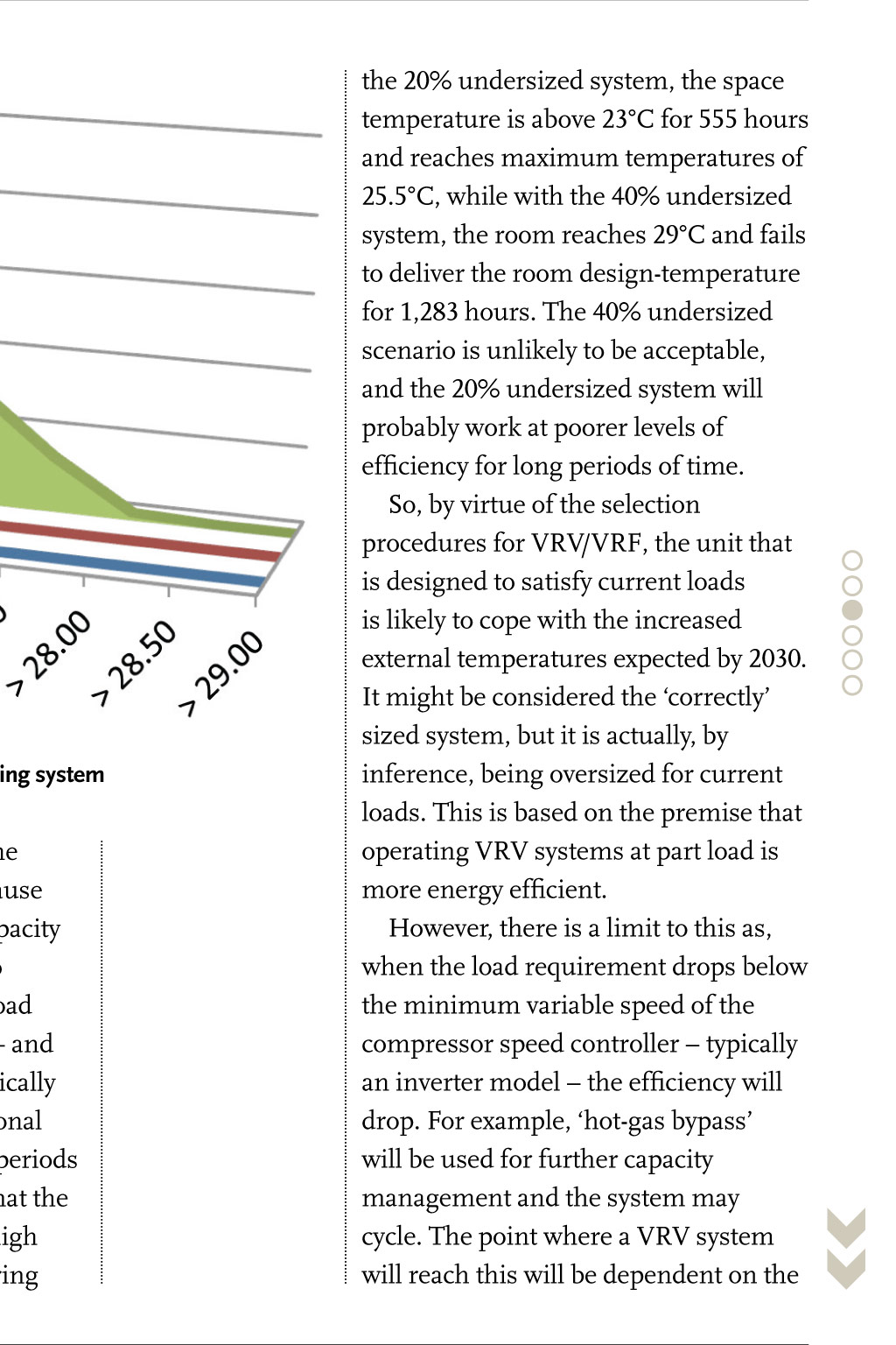
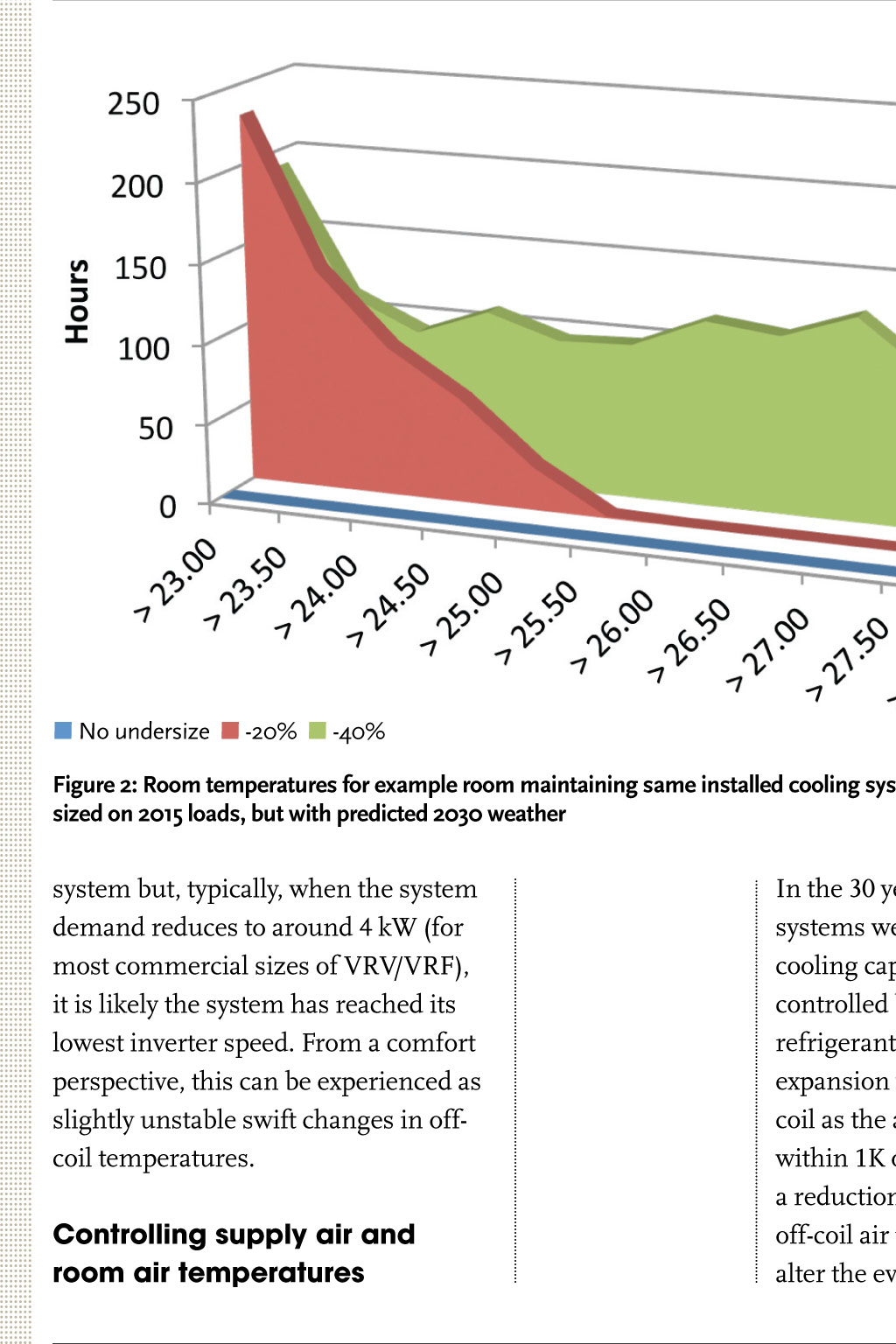
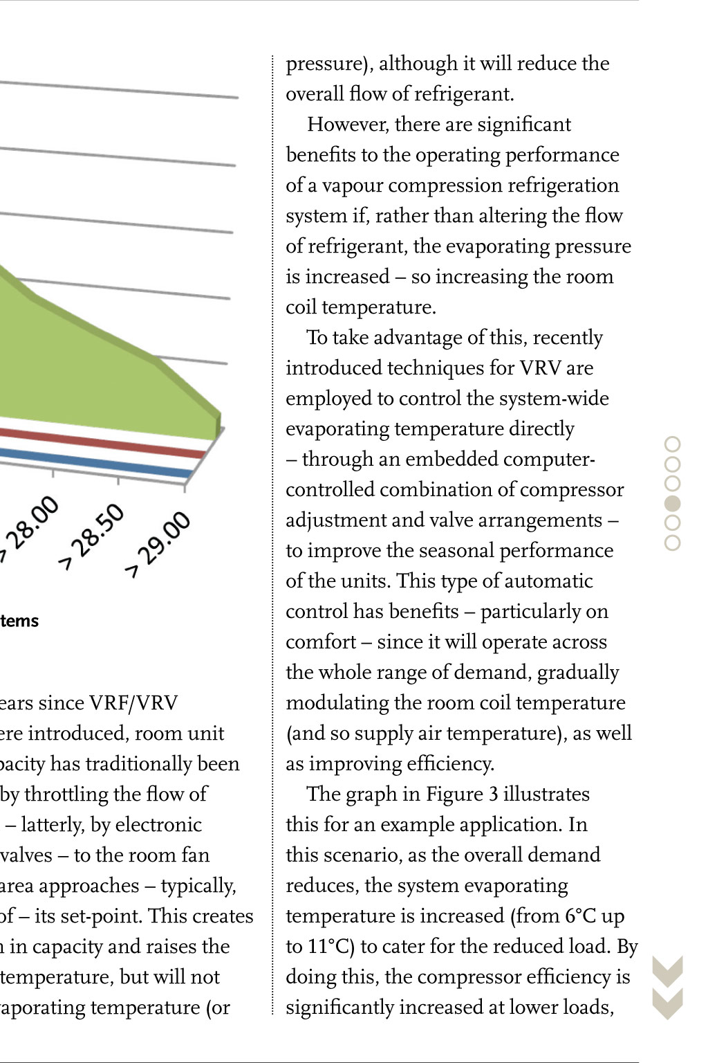
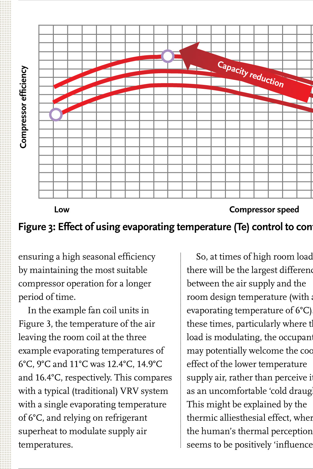
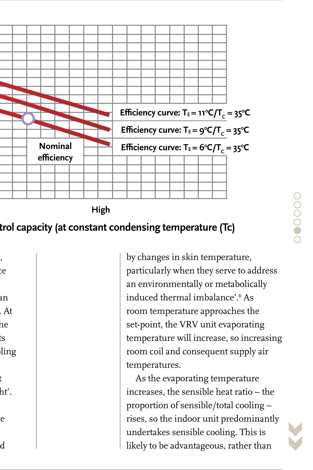
CPD PROGRAMME Maintaining comfort, as well as efficiency, with VRV systems Professional development This module explores the provision of VRV systems to provide efficient, comfortable cooling throughout their lifetime, as demands change The CIBSE Journal CPD Programme Members of the Chartered Institution of Building Services Engineers (CIBSE) and other professional bodies are required to maintain their professional competence throughout their careers. Continuing professional development (CPD) means the systematic maintenance, improvement and broadening of your knowledge and skills, and is therefore a long-term commitment to enhancing your competence. CPD is a requirement of both CIBSE and the Register of the Engineering Council (UK). CIBSE Journal is pleased to offer this module in its CPD programme. The programme is free and can be used by any reader. This module will help you to meet CIBSEs requirement for CPD. It will equally assist members of other institutions, who should record CPD activities in accordance with their institutions guidance. Simply study the module and complete the questionnaire on the final page, following the instructions for its submission. Modules will be available online at www.cibsejournal.com/cpd while the information they contain remains current. You can also complete the questionnaire online, and receive your results by return email. CPD QUESTIONNAIRE To take part in this months CPD, simply read through the module here, then follow the link at the bottom of this section. Alternatively, visit www.cibsejournal.com/cpd You will receive notification by email of successful completion, which can then be used to validate your CPD records. the required load, so the controlled space will not meet its design condition. The deviation is dependent on the configuration of the system and its actual capacity. In a multisplit or VRV system, any deficiency in available capacity is likely to have the greatest impact in the room units that are most distant (in terms of overall refrigerant pipe pressure drop) from the compressor. Those rooms will be least likely to meet their design setpoint during periods when the central plant is unable to meet the combined load of all the room units. In typical VRV applications, such as offices in temperate climatic zones, the peak cooling load usually occurs only for a short period of time typically between 2pm and 4pm, where building cooling loads are sensitive to solar gain and this would be for just a few summer days. If the system was slightly The design and application of variable refrigerant volume/variable refrigerant flow (VRV/VRF) systems has been explored in previous CPD articles. This CPD will consider the provision of VRV systems to provide comfortable cooling efficiently throughout the lifetime of the system, taking into account both current demands and the increase in loads that climate change is predicted to bring. Occupant comfort is the principal purpose in the design of many HVAC solutions. It is thought to be common practice that equipment is oversized at the design stage to ensure capacity can be met both now and in the future, as well as ensuring that the VRV units operate at optimum efficiency for the majority of their operational lifetime. In a recent analysis1 of sampled European applications of heating and cooling delivered by VRV equipment, 80% of the systems never exceeded 50% of installed capacity. The sample set included many different applications. However, the majority were installed in hotels that, by their very nature, tend to be designed for full occupancy although that is consistently not the case.2 undersized, this might mean that the controlled internal temperature would rise by less than 1K above design. Since such days would be hotter than a normal day, this may well not be noticed by the occupants as they adapt to the external climate. The period of under-cooling may still fall within reasonable limits as defined by annex G of the comfort standard EN 152513 and so meet comfort criteria. (For a discussion of human adaptation to increased internal temperatures, see CIBSE Knowledge Series 16, How to manage overheating in buildings.) However, the actual period and magnitude of deviation will be dependent on the application. To explore the consequences of undersized systems, the following simulations4 have been undertaken for a large openplan area within an office building. The room design temperature is 23C at the lower end of the range recommended by EN 15251 for an air-conditioned office space. Figure 1 illustrates the output, based on three example installed system capacities: l A VRV system that has been selected using current selection methods to match or, indeed, slightly exceed the room load. A VRV system will typically function most efficiently when operating below full capacity l A VRV system with a capacity of 80% peak load (that is, 20% undersized) l A VRV system with a capacity of 60% peak load (that is, 40% undersized). The output from the model indicates that the system designed to meet and, typically, slightly exceed the peak room load would, as might be expected, provide room temperatures maintaining the design set-point (as shown by the red line). When a system is undersized to meet just 80% of peak load, the room exceeds the desired room temperature for 224 hours and reaches a peak of 24.5C. Depending on the rationale behind setting a (reasonably moderate) room design setpoint of 23C, this could well be seen as providing reasonable levels of comfort for most of the time. With a system undersized by 40%, the room reaches 28C on the hottest modelled days and exceeds the room set-point temperature of 23C for 1,158 hours per annum. For many occupants, this is unlikely to be acceptable for an air-conditioned space. Figure 1: Room temperatures for example room with various capacities of installed cooling system load for 2030, and so maintain the design-temperature. This is because the selected system has spare capacity available to allow the system to operate most efficiently at part-load for most of its operational time and because VRV systems would typically have the ability to provide additional capacity to room units for short periods of time. It will mean, however, that the VRV compressor is running at high speed for long periods. Considering No undersize -20% -40% Figure 2: Room temperatures for example room maintaining same installed cooling systems sized on 2015 loads, but with predicted 2030 weather system but, typically, when the system demand reduces to around 4 kW (for most commercial sizes of VRV/VRF), it is likely the system has reached its lowest inverter speed. From a comfort perspective, this can be experienced as slightly unstable swift changes in offcoil temperatures. Controlling supply air and room air temperatures Climate change However, a VRV system lifespan is likely to be 15 years. As a check the 20% undersized system, the space temperature is above 23C for 555 hours and reaches maximum temperatures of 25.5C, while with the 40% undersized system, the room reaches 29C and fails to deliver the room design-temperature for 1,283 hours. The 40% undersized scenario is unlikely to be acceptable, and the 20% undersized system will probably work at poorer levels of efficiency for long periods of time. So, by virtue of the selection procedures for VRV/VRF, the unit that is designed to satisfy current loads is likely to cope with the increased external temperatures expected by 2030. It might be considered the correctly sized system, but it is actually, by inference, being oversized for current loads. This is based on the premise that operating VRV systems at part load is more energy efficient. However, there is a limit to this as, when the load requirement drops below the minimum variable speed of the compressor speed controller typically an inverter model the efficiency will drop. For example, hot-gas bypass will be used for further capacity management and the system may cycle. The point where a VRV system will reach this will be dependent on the No undersize -20% -40% against the predicted impact of climate change, a weather file for the same location has been applied to the model, using predicted data for the year 2030 from IPCC climate model A1B5 33 percentile a reasonably conservative prediction of climatic temperature change. The output of this is illustrated in Figure 2. The system that was sized to meet and slightly exceed the present day loads is still able to meet the predicted System sizing to meet lifetime loads An oversized system that employs variable volume direct expansion refrigeration will operate the compressor more slowly when it is running at part load (as there will be less refrigerant flow). This will improve compression efficiency and is also likely to increase the component life. Typically, VRV/VRF systems will be selected and installed with peak operating capacities beyond the maximum concurrent design room loads, to take advantage of this improved part-load performance. An undersized system, at times of high demand, will not be able to meet In the 30 years since VRF/VRV systems were introduced, room unit cooling capacity has traditionally been controlled by throttling the flow of refrigerant latterly, by electronic expansion valves to the room fan coil as the area approaches typically, within 1K of its set-point. This creates a reduction in capacity and raises the off-coil air temperature, but will not alter the evaporating temperature (or pressure), although it will reduce the overall flow of refrigerant. However, there are significant benefits to the operating performance of a vapour compression refrigeration system if, rather than altering the flow of refrigerant, the evaporating pressure is increased so increasing the room coil temperature. To take advantage of this, recently introduced techniques for VRV are employed to control the system-wide evaporating temperature directly through an embedded computercontrolled combination of compressor adjustment and valve arrangements to improve the seasonal performance of the units. This type of automatic control has benefits particularly on comfort since it will operate across the whole range of demand, gradually modulating the room coil temperature (and so supply air temperature), as well as improving efficiency. The graph in Figure 3 illustrates this for an example application. In this scenario, as the overall demand reduces, the system evaporating temperature is increased (from 6C up to 11C) to cater for the reduced load. By doing this, the compressor efficiency is significantly increased at lower loads, Compressor efficiency Capa city redu ction Efficiency curve: TE = 11oC/TC = 35oC Efficiency curve: TE = 9oC/TC = 35oC Nominal efficiency Low Compressor speed Efficiency curve: TE = 6oC/TC = 35oC High Figure 3: Effect of using evaporating temperature (Te) control to control capacity (at constant condensing temperature (Tc) ensuring a high seasonal efficiency by maintaining the most suitable compressor operation for a longer period of time. In the example fan coil units in Figure 3, the temperature of the air leaving the room coil at the three example evaporating temperatures of 6C, 9C and 11C was 12.4C, 14.9C and 16.4C, respectively. This compares with a typical (traditional) VRV system with a single evaporating temperature of 6C, and relying on refrigerant superheat to modulate supply air temperatures. unnecessarily dehumidifying the room air. Eliminating cold draughts It is, of course, possible to design for the complete elimination of cold draughts from VRV systems. If the system is designed to operate permanently at a higher evaporating temperature, the supply air levels are always above a pre-determined value. However, compared with a system that varies the evaporating temperature with the load, a system with a high fixed evaporating temperature will require larger room fan coils. Some systems can maintain offcoil temperatures by using a sensor that monitors the off-coil temperature, and then closes the expansion valve on the fan coil to restrict the capacity. These systems are not suitable for the standard target evaporating condition of 6C, as they could prematurely close the expansion valve to try to satisfy off-coil temperature before the room set-point had been met. So, through appropriate design and selection, it is possible to provide VRV systems that not only deliver appropriately comfortable supply air temperatures, but also have both the So, at times of high room load, there will be the largest difference between the air supply and the room design temperature (with an evaporating temperature of 6C). At these times, particularly where the load is modulating, the occupants may potentially welcome the cooling effect of the lower temperature supply air, rather than perceive it as an uncomfortable cold draught. This might be explained by the thermic alliesthesial effect, where the humans thermal perception seems to be positively influenced flexibility and capacity to satisfy cooling demands across their operational life, while delivering acceptable seasonal efficiencies. Tim Dwyer, 2014. by changes in skin temperature, particularly when they serve to address an environmentally or metabolically induced thermal imbalance.6 As room temperature approaches the set-point, the VRV unit evaporating temperature will increase, so increasing room coil and consequent supply air temperatures. As the evaporating temperature increases, the sensible heat ratio the proportion of sensible/total cooling rises, so the indoor unit predominantly undertakes sensible cooling. This is likely to be advantageous, rather than http://epp.eurostat.ec.europa.eu/statistics_ explained/index.php/Tourism_statistics_-_ occupancy_rates_in_hotels_and_similar_ establishments accessed 30th November 2014 3 Indoor environmental input parameters for l We gratefully acknowledge the input of Richard Green, VRV specialist in the product management and engineering group, Daikin UK, for developing IES models and providing core materials for this CPD article. design and assessment of energy performance of buildings addressing indoor air quality, thermal environment, lighting and acoustics EN 15251:2007. 4 Results of simulation undertaken by Daikin employing IES Virtual Environment software, November 2014. REFERENCES: 5 www.ipcc.ch/publications_and_data/ar4/ 1 Daikin unpublished internal research syr/en/spms3.html report. See http://www.ipcc.ch/ 6 Parkinson, T., et al, Perception of publications_and_data/ar4/syr/en/spms3. transient thermal environments: pleasure and html for discussion of these weather alliesthesia, Proceedings of 7th Windsor scenarios Conference: The changing context of 2 Tourism statistics occupancy rates in hotels comfort in an unpredictable world London, and similar establishments, April 2012. Module 72 - January 2015 Fill in this months questionnaire online. You will receive notification by email of successful completion, which can then be used to validate your CPD records in accordance with your institutions guidance. CLICK HERE TO FILL IN THE QUESTIONNAIRE "